
Mastering NX Assemblies: How to Use 'Move Component' for Arrangements (Without Constraints)
If you are an "OG" Siemens NX user, you probably remember how easy it used to be to set up multiple positional states in an assembly. You would open up the Move Component dialog, spin your geometry, and look for a handy little button that said "Apply to Used." But if you expand that same dialogue window in modern versions of NX, that button is completely gone.
So, how do you show an assembly in different positional states—like an enclosure door swinging from closed to open, or a cylinder extending—if you only want to use the Move Component tool without building a complex web of assembly constraints?
In this quick guide, we’re going to look at the modern equivalent of the "Apply to Used" command and how to lock down unique positional states using Assembly Arrangements.
Watch the Video!
The Goal: Pure Positional States
For this exercise, we are assuming a completely clean slate. If you look at our Constraint Navigator, there are zero active constraints holding the components together. The objective is simply to move the geometry around manually and isolate those specific movements so they apply exclusively to their active arrangement.
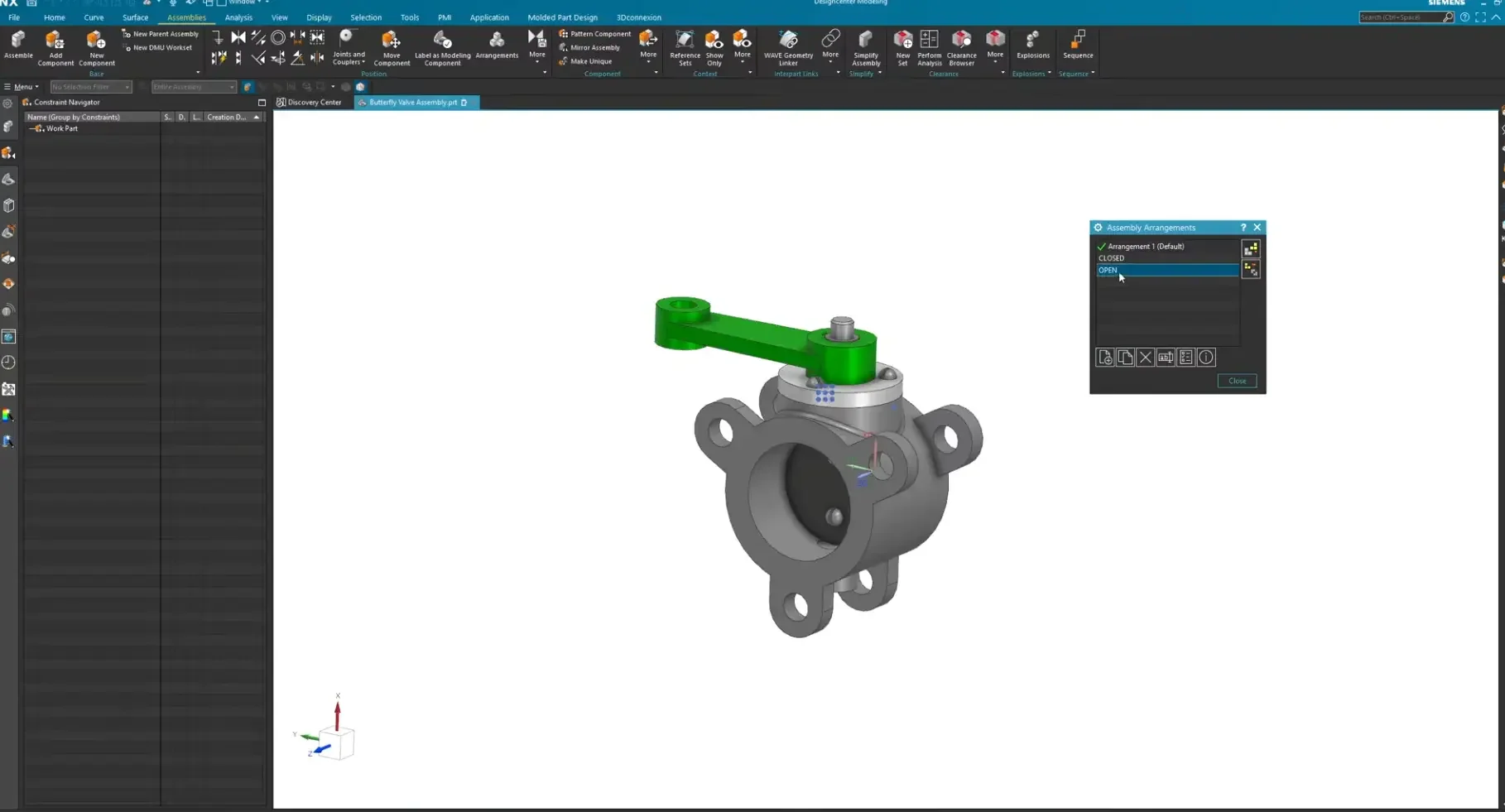
Step 1: Initialize Your Arrangements
Before moving a single piece of geometry, you need to establish your assembly variants.
Navigate to the Assemblies ribbon and select the Arrangements icon.
Create two distinct configurations. For this tutorial, we will use "CLOSED" and "OPEN".
Double-click on "OPEN" to make it your active arrangement. You will see a green checkmark appear next to it.
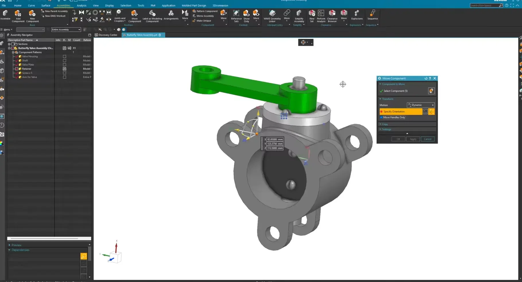
Step 2: Set Up Your Component Selection
Next, we need to gather all the parts that will move together as a single kinematic unit.
Change your Selection Filter in the top bar to Component.
Select all corresponding geometry (e.g., the plates, hardware screws, shaft, and arm).
Launch the Move Component command.
Step 3: Align the Transform Handle (Optional)
Often, when you select multiple unconstrained parts, the movement triad (handle) defaults to a position that isn’t ideal for clean rotation.
In the Move Component dialog, turn on the Move Handles Only checkbox. This allows you to reposition the triad without dragging your geometry along with it.
Enable your cursor Snap Points, grab the center of the triad, and snap it cleanly to the rotational axis of your pivoting component.
Turn Move Handles Only back off once the handle is properly centered.
Step 4: Reposition the Geometry
With your triad centered, rotate or translate your components into the new position. For instance, drag the handle to swing the mechanism open precisely 90 degrees.
Step 5: The Modern "Apply to Used" Equivalent
Here is where the solution to our mystery lives. To record this change for the open position only, look at the bottom sections of the Move Component dialog box.
Expand the Settings or Position drop-down menus.
Locate the section labeled: Arrangement Target for Current Work Part.
Switch the active radio button to: Apply to Active Arrangement.
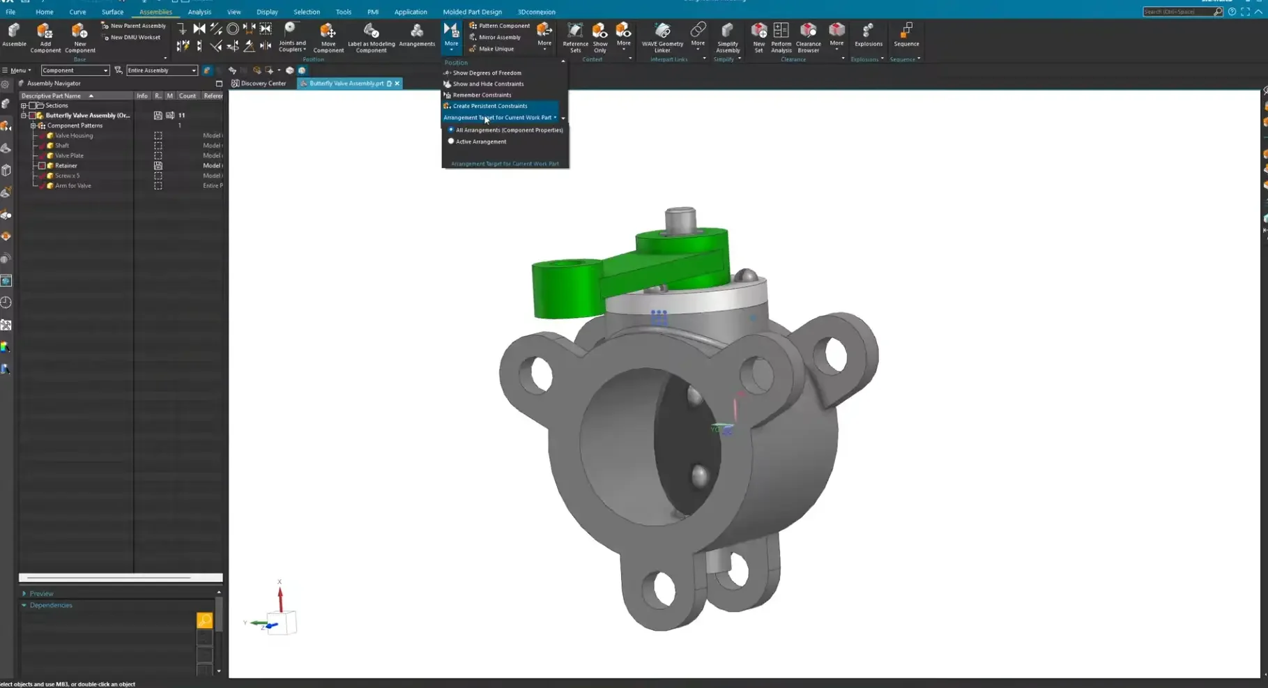
By selecting this, you are hard-coding this specific translation to the "OPEN" arrangement state only. Click OK to execute.
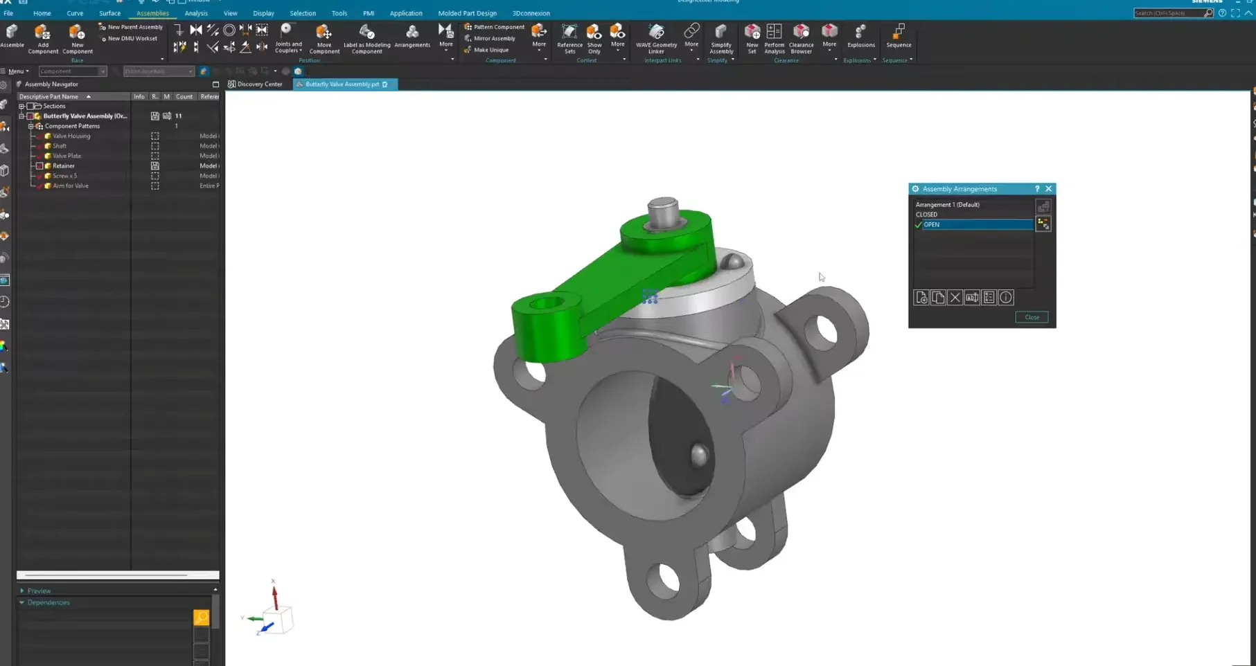
Verifying Your Workflow Success
To test the parametric logic, open your Assembly Navigator or the Arrangements manager:
Double-click on CLOSED . The components snap back to their default, unrotated baseline position.
Double-click on OPEN. The components dynamically swing out 90 degrees to the secondary state.
Whether your downstream items are fully constrained or completely free-floating, leveraging the Arrangement Target setting ensures that you can rapidly build design configurations without over-complicating your part files.
Next Steps: Deepen Assembly Control & Component Management
Configuring independent movement paths completely redefines how your team builds dynamic, multi-state assemblies. Complete your mastery of complex layout configurations with these advanced Siemens NX guides:
Deconstruct Assembly Display Types: Never confuse positional changes with geometry display settings again. Master the exact differences and ideal workflows using our deep-dive on Arrangements vs Reference Sets.
Maintain Constraints Across Moving Parts: Safely publish and update critical component data between multi-positional models without breaking your geometry links by exploring the Product Interface Command in Siemens NX.
Scale These Workflows Across Your Engineering Team
Standard software tutorials only go so far when facing unique, real-world production bottlenecks. If your design team is struggling with workflow inefficiencies, modeling errors, or assembly instability, we can help.
At JIVE Engineering, we provide specialized, bespoke Corporate Engineering & CAD Training customized entirely around your company’s native production files and internal design standards. We move your team past basic button-clicking and equip them to build robust, failure-proof modeling workflows that save hours of engineering time.
Explore Our Custom Training Programs or Contact Our Team today to discuss your team's specific training needs.