
A Beginner’s Guide to Siemens NX CAM
Watch the Video!
Need a video to help you through this process? Then check out the video on youtube!
Transitioning from 3D modeling to CNC programming can feel like learning a completely different language. You’ve built the perfect part in CAD, but how do you actually tell a machine how to cut it?
In our latest tutorial, NX 12 CAM for Beginners, we strip away the complexity and show you the essential foundation you need before you ever hit "Generate Toolpath." If you are new to the manufacturing side of Siemens NX, this is the place to start.
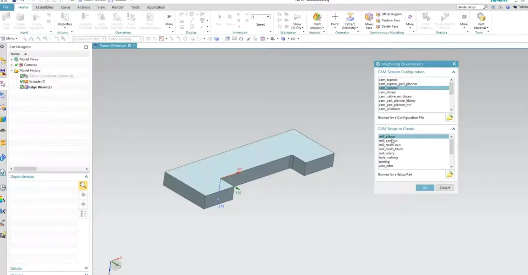
The Manufacturing Environment
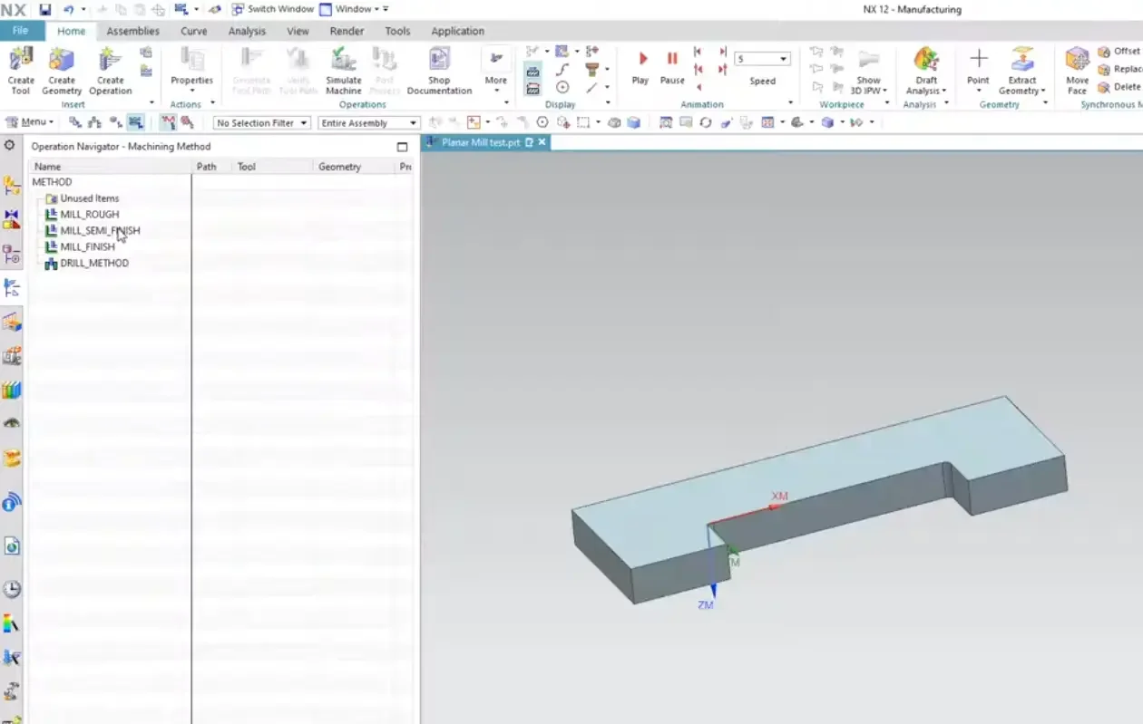
The first thing you’ll notice in NX is that "Manufacturing" is a separate application. We walk you through how to enter this environment correctly and, more importantly, how to set up your Parent Groups.
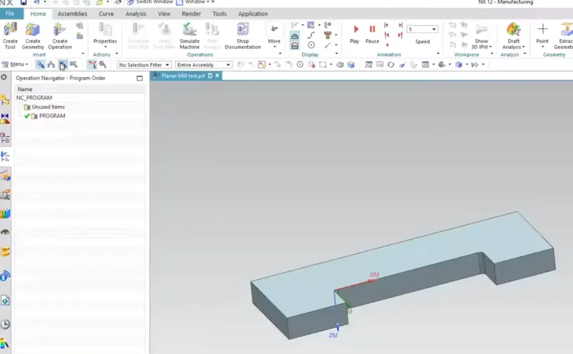
In NX CAM, everything follows a hierarchy. To get a successful program, you need to define four things:
The Program: Where your operations live.
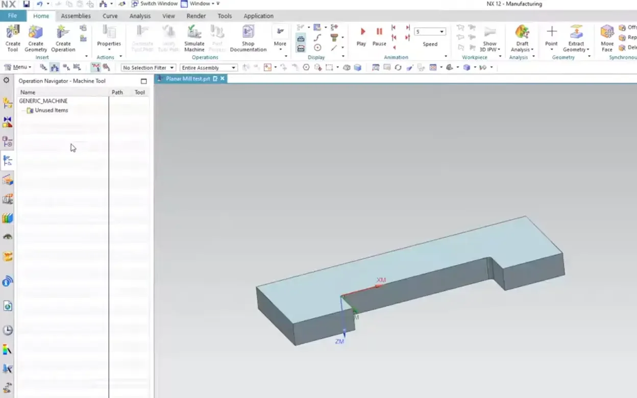
The Tool: What is doing the cutting.
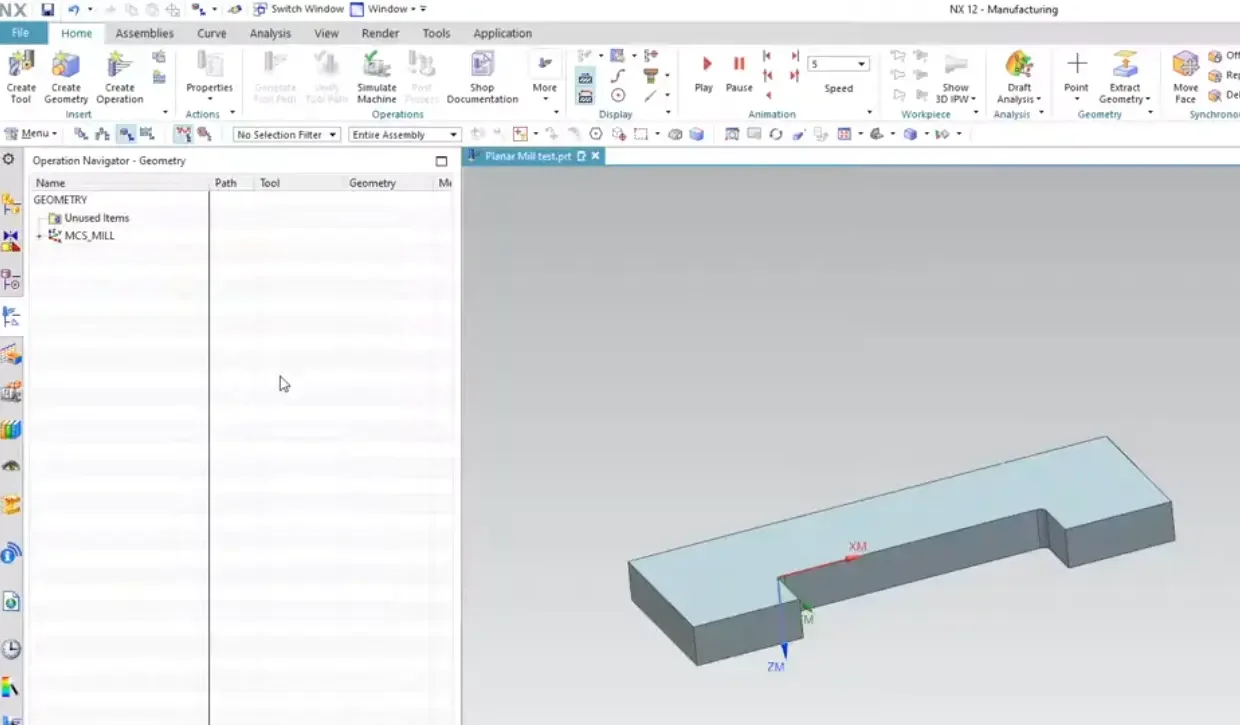
The Geometry: What is being cut (and what to avoid!).
The Method: How you are cutting (Roughing vs. Finishing).
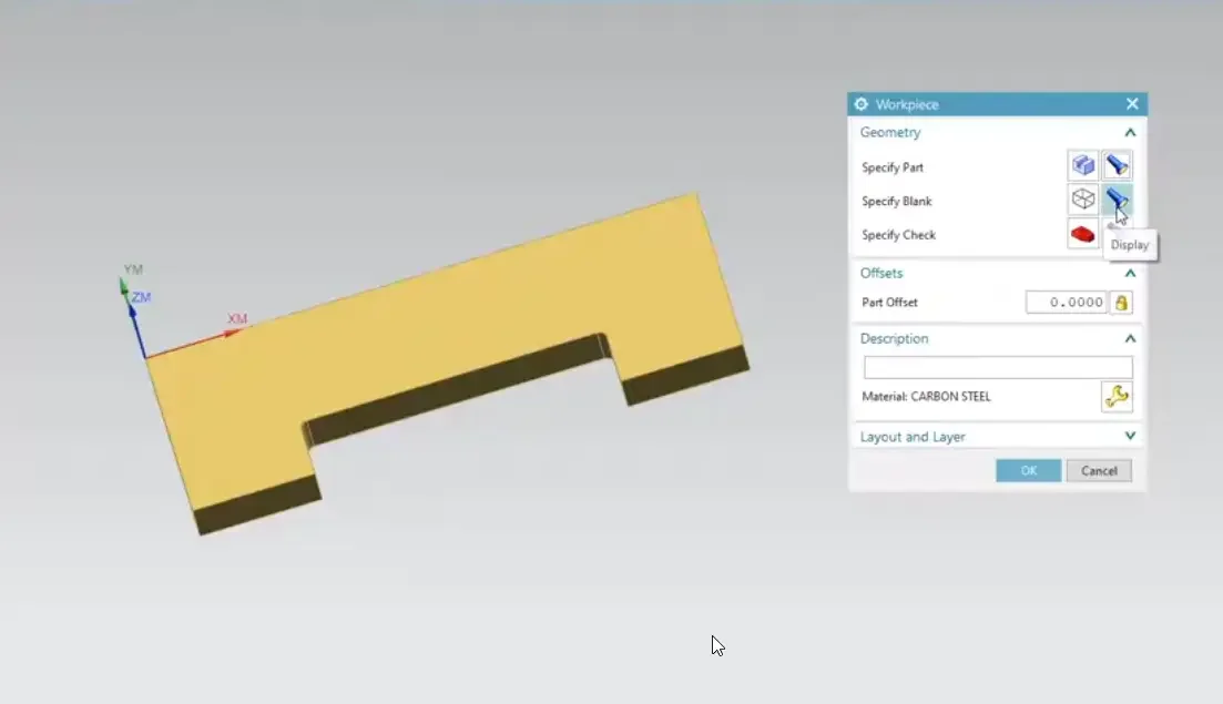
Setting Up Your MCS and Workpiece
The biggest mistake beginners make is skipping the Coordinate System (MCS) and Workpiece setup. In the video, we show you:
MCS (Machine Coordinate System): How to tell NX where "Zero" is on your machine.
The Workpiece: How to select your "Part" (the final result) and your "Blank" (the raw material you're starting with).
If you don't define these correctly, NX won't know how much material is left to remove, leading to inefficient toolpaths or, worse, crashes.
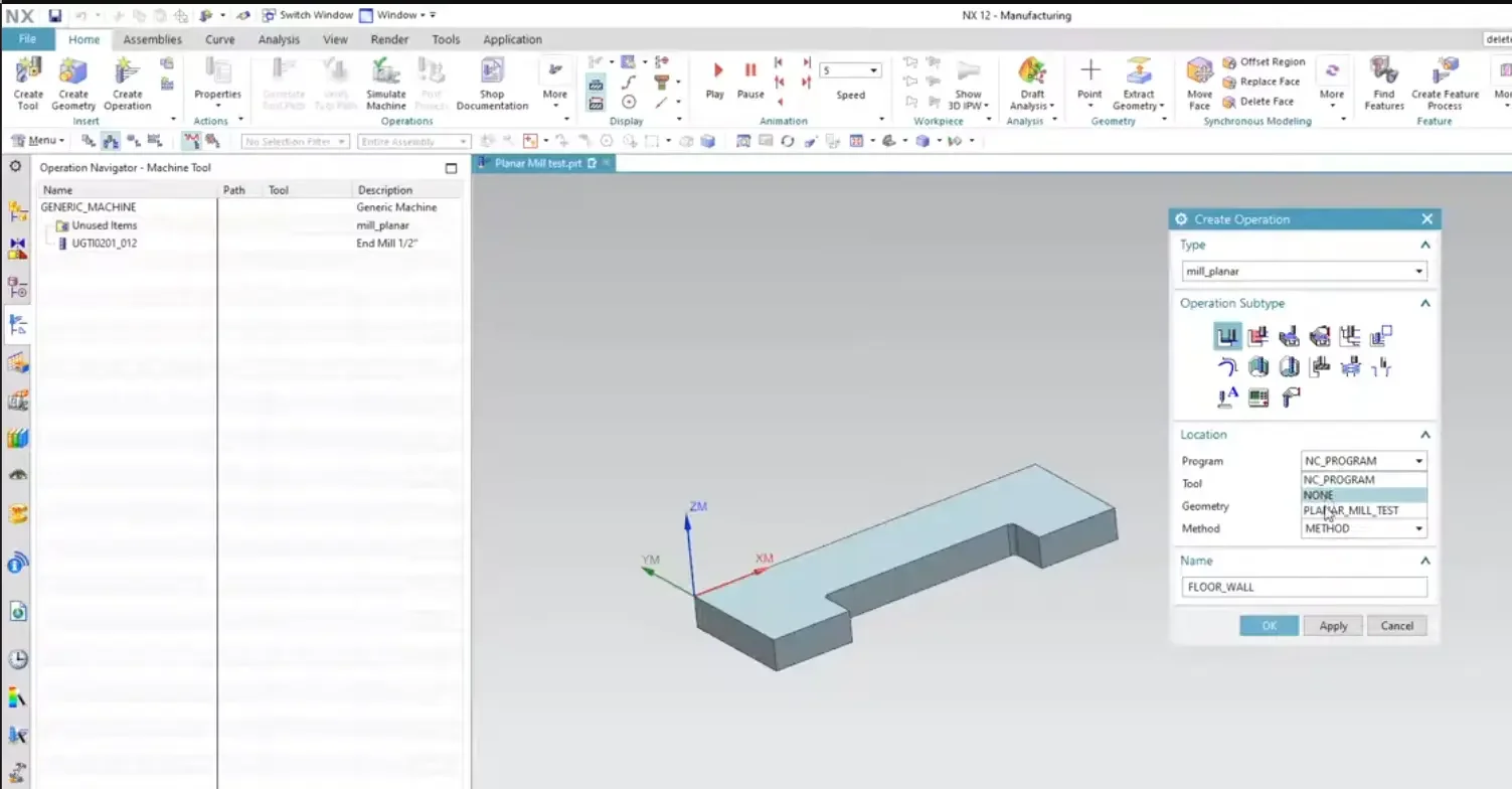
Your First Operation: Face Milling
Once the foundation is set, we walk through a basic operation. You’ll learn how to select a tool from the library, set your cut levels, and generate your first visible toolpath. Seeing those blue and red lines appear for the first time is a game-changer!
Why This Matters
Siemens NX is incredibly powerful, but that power comes with many buttons and menus. By focusing on the Operation Navigator and the core setup steps, you can start programming parts with confidence instead of just clicking and hoping for the best.
Watch the Full Beginner Tutorial
Ready to turn your 3D models into real-world parts? Check out the full video to follow along step-by-step.
Next Steps: Execute Your First Toolpaths & Prep Part Files
Navigating the basic manufacturing environment is just the foundation. Take your programming skills onto the shop floor and start cutting metal with these essential step-by-step NX CAM guides:
Program Basic Pocketing and Facing Routines: Learn how to apply your very first 2.5-axis roughing and finishing operations using our complete tutorial on How to Use Planar Mill in NX CAM.
Clean Up Models for Seamless Machining: Stop fighting uncooperative geometries or broken features. Discover how to cleanly isolate and structure files before drilling using Preparing Hole Geometry for CAM in Siemens NX.
Scale These Workflows Across Your Engineering Team
Standard software tutorials only go so far when facing unique, real-world production bottlenecks. If your design team is struggling with workflow inefficiencies, modeling errors, or assembly instability, we can help.
At JIVE Engineering, we provide specialized, bespoke Corporate Engineering & CAD Training customized entirely around your company’s native production files and internal design standards. We move your team past basic button-clicking and equip them to build robust, failure-proof modeling workflows that save hours of engineering time.
Explore Our Custom Training Programs or Contact Our Team today to discuss your team's specific training needs.