
How to Use the Product Interface Command in Siemens NX
Watch the Video!
Need a video to help you through this process? Then check out the video on youtube!
In the world of complex engineering, "isolated" design is a recipe for disaster. If you are designing a bracket that attaches to an engine block, you need to know exactly where the bolt holes are—but you don’t necessarily want to load the entire engine model into your session.
This is where the Product Interface in Siemens NX comes in. It is one of the most powerful tools for managing inter-part relationships and ensuring that your assemblies are both stable and easy to navigate.
What is a Product Interface?
A Product Interface is a way to "publish" or "expose" specific geometry from a part so that it can be easily referenced by other parts in an assembly. Think of it as creating a "public menu" for your part. Instead of another designer digging through your internal features, sketches, and datums, they only see the specific items you’ve designated as "Interface" objects.
Why Use Product Interface instead of simple Wave Linking?
While you can simply Wave Link geometry between parts, using a Product Interface adds a critical layer of control:
Selection Intent: It clearly communicates to other team members which geometry is intended to be used for mounting or clearance.
Stability: If you change the internal features of your part but keep the Product Interface the same, the downstream parts that reference it won’t break.
Ease of Use: When another user goes to create a link, they don't have to search through a messy Part Navigator; the Product Interface folder gives them exactly what they need.
Key Steps Covered in the Tutorial
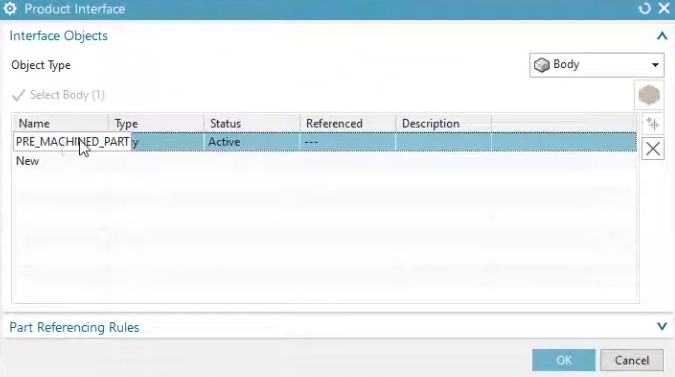
1. Creating the Interface
In the video, we show you how to navigate to the Product Interface command. From there, you can select:
Outputs: Geometry (faces, edges, points) that you want to give to other parts.
Inputs: References that your part needs from other components.

2. Managing the Interface Folder
Once created, these objects appear in a dedicated Product Interface folder at the top of your Part Navigator. This makes it incredibly easy for any designer to see the "inputs and outputs" of a component at a glance.

3. Creating Downstream Links
We demonstrate how, when you are in a different part within the assembly, you can use the WAVE Geometry Linker to select from the "Product Interface" list rather than hunting for raw geometry in the graphics window.
Best Practices for Top-Down Design
Using Product Interfaces is a hallmark of a professional NX workflow. It allows for:
Parallel Engineering: Multiple designers can work on different parts of an assembly simultaneously, confident that their interfaces will match up.
Reduced File Sizes: You can reference the interface without needing to load every single feature of the source part.
Watch the Full Walkthrough
If you want to move beyond basic modeling and start building professional, associative assemblies, this is a must-watch tutorial. We dive into the menus and show you the exact clicks to get started.
Next Steps: Master Top-Down Assembly Control & Interpart Links
Publishing clean product interfaces is key to building modular, reliable CAD architectures. Take complete control of your large multi-part assemblies and associative links with these advanced NX tutorials:
Deploy Secure Interpart Connections: Take your interface references to the next level and discover how to copy, update, and manage global geometry across complex files seamlessly with our guide on Mastering Top-Down Design How to Use NX WAVE Mode.
Position Interlinked Assemblies Dynamically: Once your parts are structurally connected via interface layers, control their physical range of motion and design variations using How to Use Move Component with Arrangements.
Scale These Workflows Across Your Engineering Team
Standard software tutorials only go so far when facing unique, real-world production bottlenecks. If your design team is struggling with workflow inefficiencies, modeling errors, or assembly instability, we can help.
At JIVE Engineering, we provide specialized, bespoke Corporate Engineering & CAD Training customized entirely around your company’s native production files and internal design standards. We move your team past basic button-clicking and equip them to build robust, failure-proof modeling workflows that save hours of engineering time.
Explore Our Custom Training Programs or Contact Our Team today to discuss your team's specific training needs.