
Mastering Top-Down Design: How to Use NX WAVE Mode
Watch the Video!
Need a video to help you through this process? Then check out the video on YouTube!
If you’ve ever found yourself creating empty "dummy" assemblies just to link geometry between parts, you know it can be a hassle. It clutters your file structure with unnecessary assembly part numbers and complicates your workflow.
Enter WAVE Mode.
WAVE Mode in Siemens NX allows you to share geometry between parts associatively—completely independent of their assembly position. It lets a "Parent" part drive the geometry of multiple "Child" parts without the overhead of a traditional assembly structure.
In this guide, we’ll walk through how to activate, use, and manage WAVE Mode relationships.
Prerequisite: The License Check
Before diving in, note that WAVE Mode requires a specific license. You can quickly check if you have it by attempting to activate the mode (step 1 below). If it lets you toggle it on, you’re good to go!
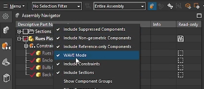
Step 1: Activating WAVE Mode
By default, WAVE Mode might be hidden. To turn it on:
- Open your Assembly Navigator.
- Right-click on the Descriptive Part Name column header (or in the white space of the navigator).
- Look for Wave Mode in the context menu.
- Select it to toggle it on. You should see a checkmark next to it, confirming it is active.
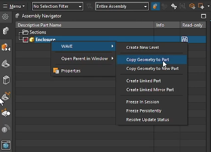
Step 2: Creating the Link (Parent to Child)
The core idea of WAVE Mode is "Part-to-Part" linking. You don't need to insert the parts into an assembly file first.
- Select the Parent: Open the part you want to share data from (e.g., your enclosure or box). It helps to open this in its own window to keep things clear.
- Initiate the WAVE: In the Assembly Navigator, right-click on the name of the part.
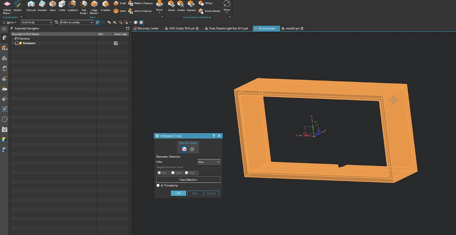
- Navigate to Wave > Copy Geometry to Part.
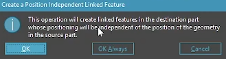
- NX will display the following warning. This warning is stating that features will be copied, but assembly position is ignored. This makes sense, as there is no assembly in this instance. Select OK.
- Choose the Destination:
- If you already have a destination part created, select it.
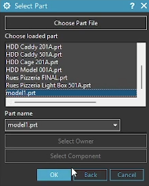
- Select Geometry: A dialog will appear asking what you want to copy. You can select curves, sketches, or entire solid bodies. Select your target body and click OK. Use the selection filter to your advantage.
You now have an associative copy of the parent body inside your new child part (Model1).
Step 3: Understanding Associativity
Once linked, it is crucial to understand the hierarchy: The Parent controls the Child, never the other way around.
- Parent Changes: If you add a feature to the Parent (like an edge blend or chamfer), the Child part will automatically update to reflect this change (provided both files are open).
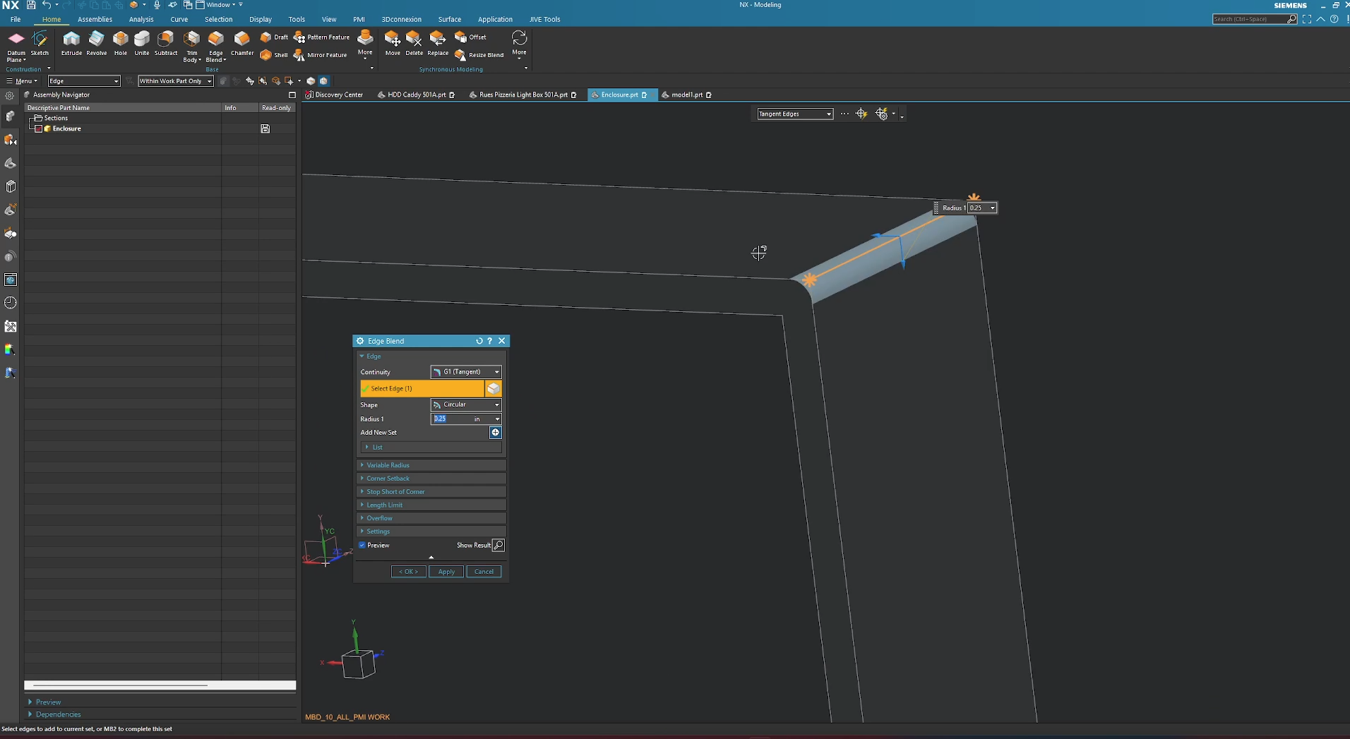
This is the parent part receiving an edge blend.
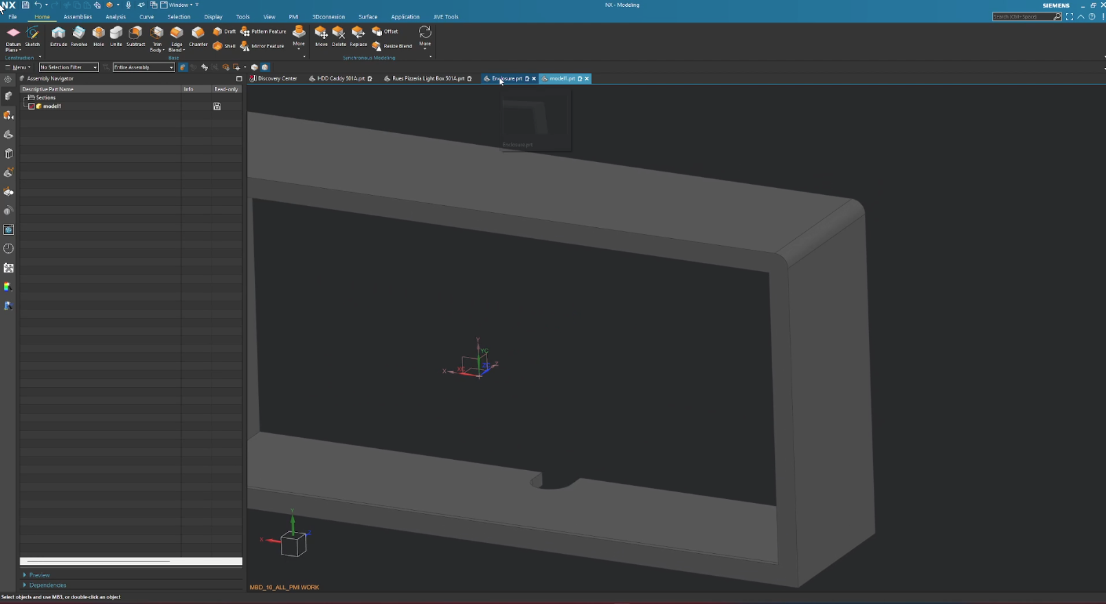
This is the child part receiving that same change.
Note: The linked body in the child part is position-independent. You can move the child body (Ctrl+T) anywhere in 3D space, and it will maintain its geometric link to the parent without snapping back to the parent's absolute coordinates.
Step 4: Breaking the Link
Sometimes you want to sever the connection to stop the Child from updating. You have two main options here:
Option A: Turn Off Associativity (The Soft Break)
Use this if you want a static body now but might want to re-link it later.
- In the Child part, double-click the Linked Body in the Part Navigator.
- Go to Settings.
- Uncheck Associative.
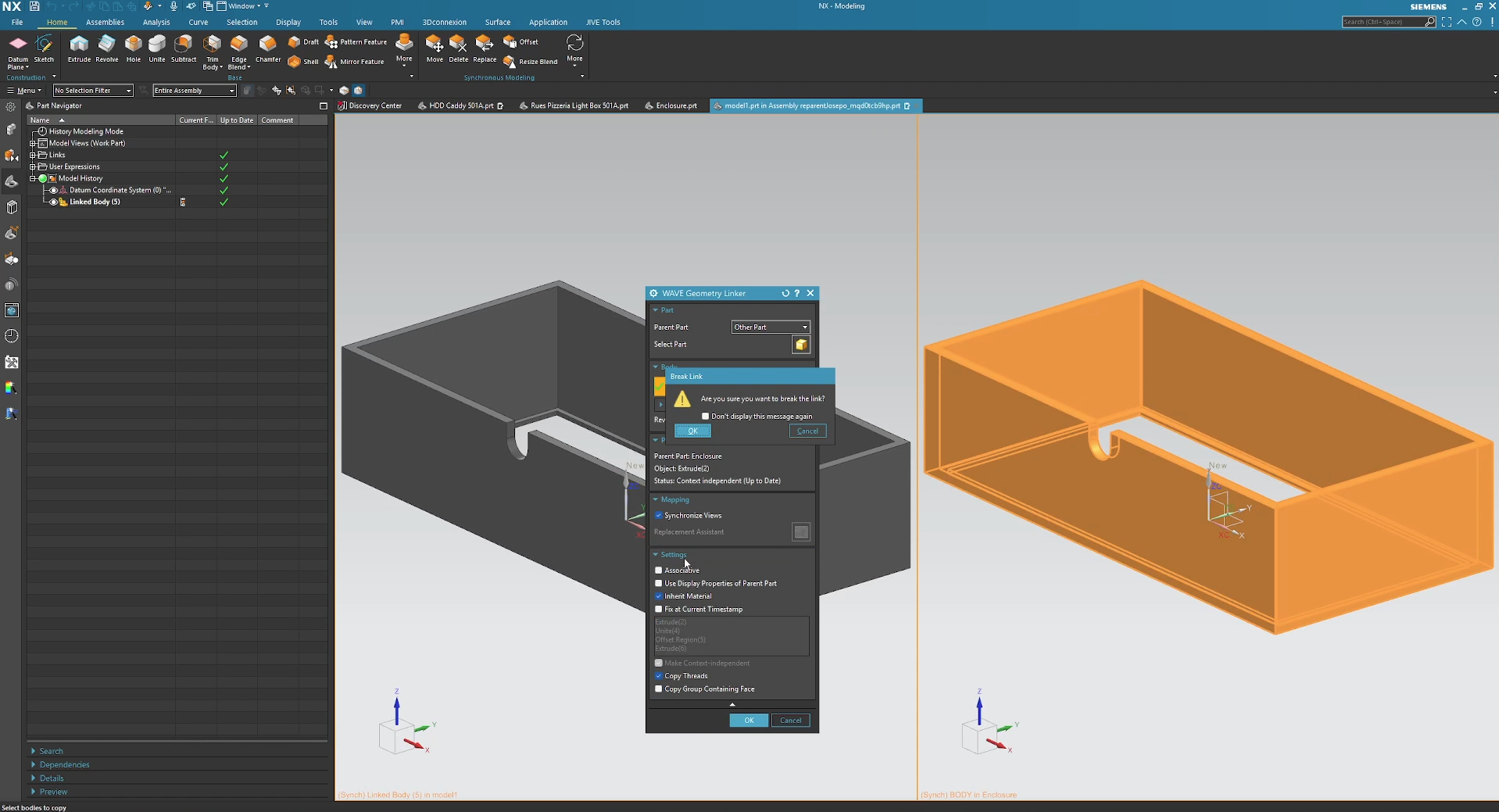
Option B: Remove Parameters (The "Nuke")
Use this if you want to completely destroy the relationship and make the body 100% independent.
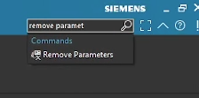
- Use the Command Finder to search for Remove Parameters.
- Select the linked body in your Child part.
- Click OK and confirm the warning.
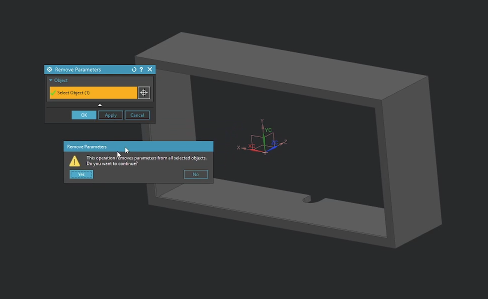
- The link is gone forever. You can now use Synchronous Modeling or standard features to edit this body without any tie to the original parent.
Summary: Why Use WAVE Mode?
Traditional assembly WAVE linking controls two things: Geometry and Position.
WAVE Mode only controls Geometry.
This distinction makes WAVE Mode incredibly powerful for workflows where you need a master shape (like a casting or a mold core) to drive multiple different downstream parts (machining stages, different SKU variations) without worrying about assembly constraints or file management overhead.
You can have one "Enclosure" parent driving Model1, Model2, and Model3 simultaneously, keeping your designs consistent and your file.
Step Up Your Siemens NX Workflow
Now that you know how to master top-down assembly design using the WAVE Geometry Linker, check out our other step-by-step guides to streamline your CAD layouts:
Automate Your Models: Learn how to configure Siemens NX Part Families to save hours on standard components and eliminate design errors.
Master Assembly WAVE Linking: Use our complete guide on the WAVE Geometry Linker for Assemblies to seamlessly create associative items in assemblies.
Standard software tutorials only go so far when facing unique, real-world production bottlenecks. If your design team is struggling with workflow inefficiencies, modeling errors, or assembly instability, we can help.
At JIVE Engineering, we provide on-site Siemens NX Corporate Training customized entirely around your company's actual production files, native geometry, and internal workflows. We help your design team transition from basic button-clicking to mastering robust, failure-proof top-down modeling strategies.
Explore Our Custom NX Training Programs or Contact Our Team today to schedule a workflow audit.