
How to Use the Siemens NX Assemble Command to Place Components Faster
Watch the Video!
Need a video to help you through this process? Then check out the video on YouTube!
If you’ve been using Siemens NX for a while, you’re likely intimately familiar with the traditional Assembly Constraints dialog. It’s powerful, but it can feel heavy with clicks. In NX 2206, Siemens emphasized a newer, more streamlined tool: the Assemble command.
In this post, we take a deep dive into this command. While we’ve traditionally stuck to the old-school methods, the Assemble command has some hidden efficiency perks—especially for quick component placement. Here is your step-by-step guide to use it.
What is the "Assemble" Command?

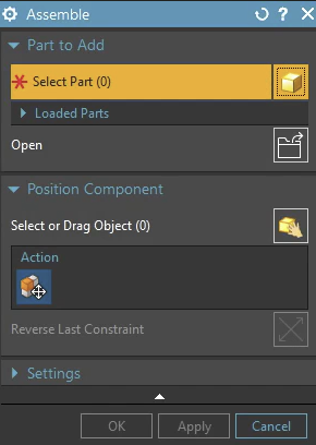
Step 1: Access the Command
You can find the Assemble command in the Assembly tab of the ribbon.
- If you can't find it, use the Command Finder and type "Assemble."
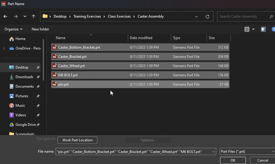
Step 2: Selecting Your Component
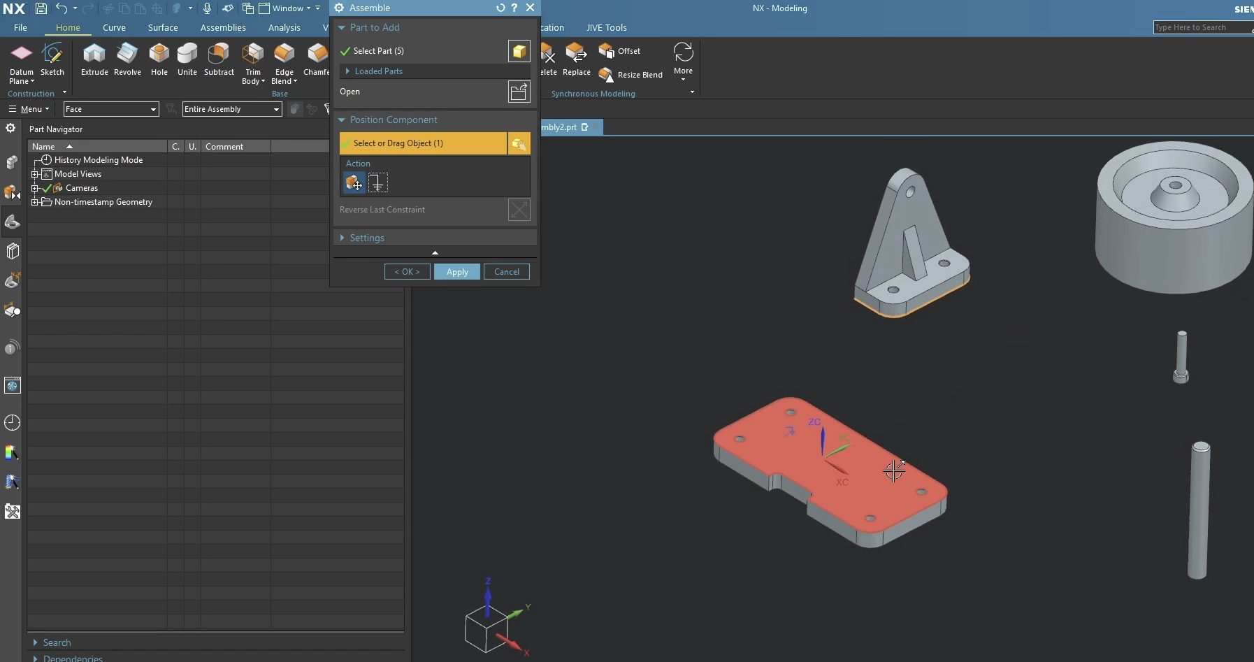
Once the dialog is open, click Open and your first step is to select the parts you want to bring into the assembly.
- You can open multiple parts in one go.
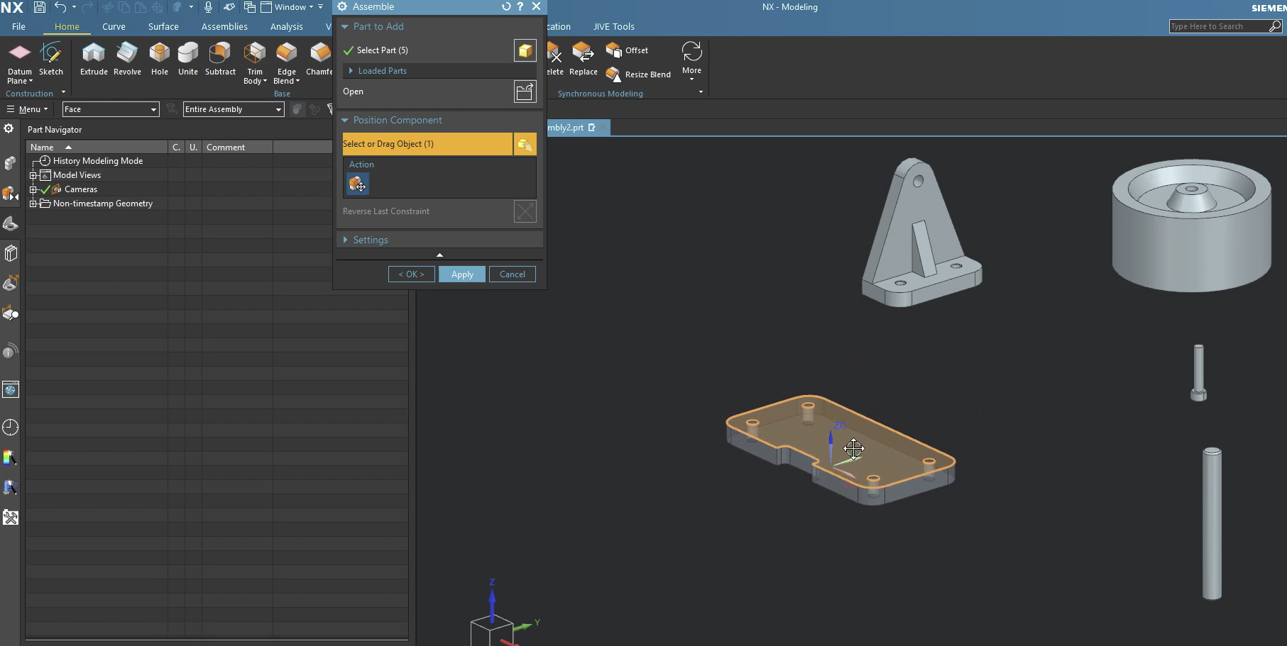
Step 3: Positioning and Dragging (The "Loose" Move)
Before applying hard constraints, you might want to get the part into the "ballpark" area.
- To Move: Click and hold the Left Mouse Button (MB1) on the part and drag it.
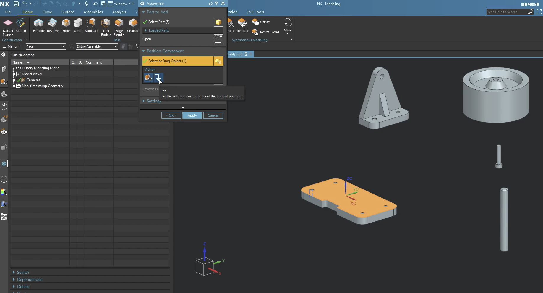
Step 4: Applying Inferred Constraints
Now let's apply constraints. First, let's fix one item. In this case, we fixed that Caster Bottom Bracket.prt.
Next, instead of picking "Touch" or "Align" from a list, just start picking geometry:
- Select a face on your moving part.

- Select a face on the stationary part.
- NX will automatically apply a Touch/Align constraint.
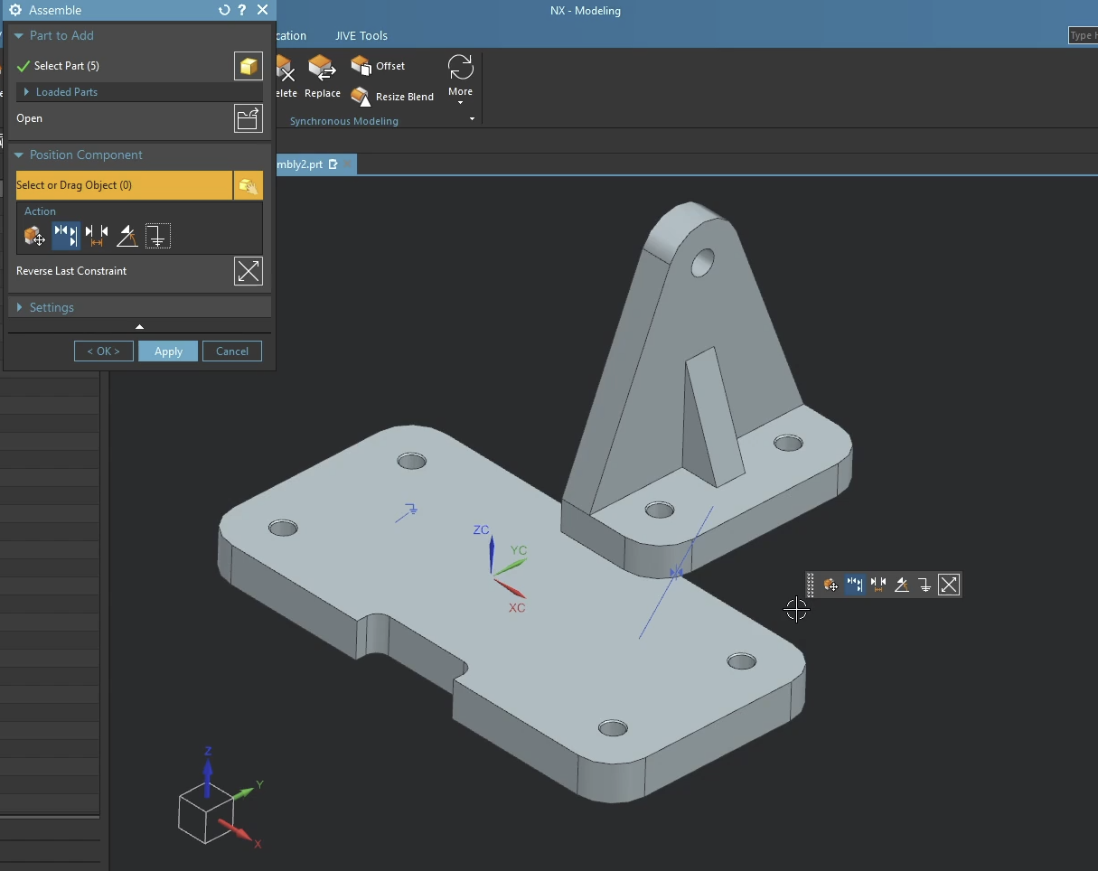
If NX picks "Touch" but you wanted "Align" (or vice versa), look for the Flip icon that appears near your cursor or in the dialog. You don't have to restart the command!
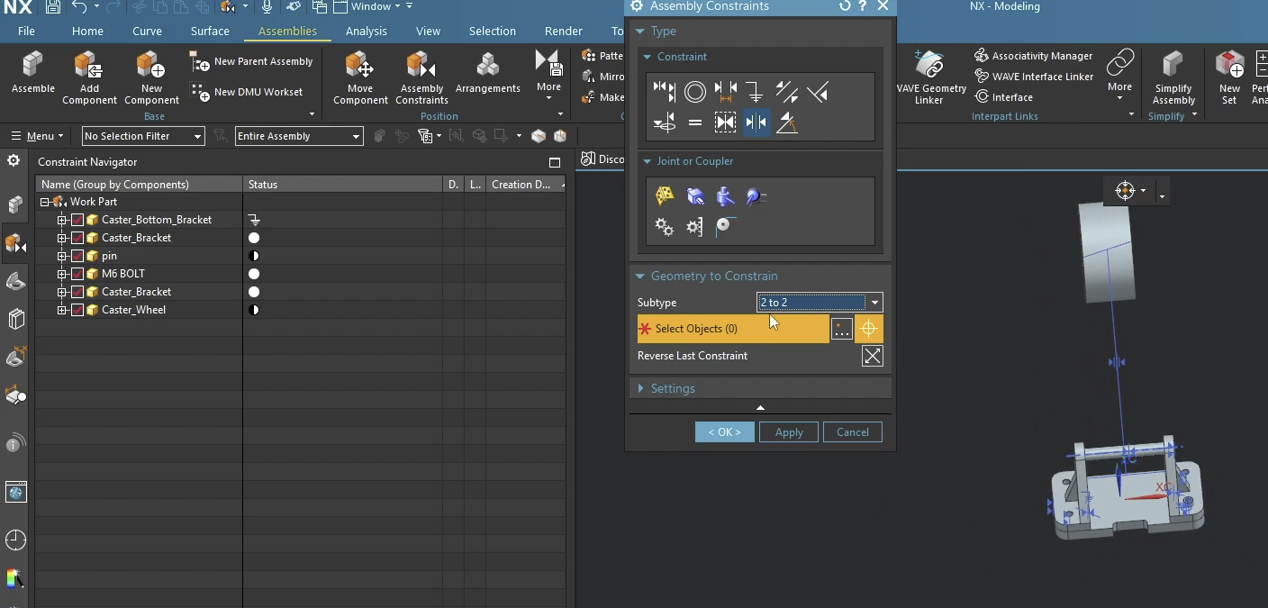
Step 5: Working with Brackets and Mid-Planes
In this post, we demonstrate a common scenario: centering a part between two faces of a bracket.
- This is where the command falls apart. There is currently no way to do this in NX 2206. Because of this, you must switch to the classical method.
The Verdict: Should You Use It?
The Assemble command is significantly faster for basic constraints and standard hardware. It feels more "modern" and less "menu-heavy."
However, for complex mechanical relationships or very specific "Distance" constraints with offsets, you might still find yourself reaching for the traditional Add Component or Assembly Constraints dialogs.
Next Steps: Optimize Your Assembly Structure
Now that you know how to rapidly snap parts into place using the modern Assemble command, take your top-down assembly structure to the next level with our advanced layout guides:
Master Top-Down Layouts: Learn how to build robust, failure-proof inter-part relationships using our step-by-step guide on How to Use the Siemens NX WAVE Geometry Linker.
Automatic Views for Documentation: For more advanced assembly documentation techniques, check out our step-by-step guide on Creating Exploded Views in Siemens NX.
Standard software tutorials only go so far when facing unique, real-world production bottlenecks. If your design team is struggling with workflow inefficiencies, modeling errors, or assembly instability, we can help.
At JIVE Engineering, we provide on-site Siemens NX Corporate Training customized entirely around your company's actual production files, native geometry, and internal workflows. We help your design team transition from basic button-clicking to mastering robust, failure-proof top-down modeling strategies.
Explore Our Custom NX Training Programs or Contact Our Team today to schedule a workflow audit.