Exploded Views in Siemens NX: A Quick Guide to Clean Assembly Documentation
Exploded views are a foundational requirement in assembly design. When you hand off a complex geometric package to production, the shop-floor operators or technical writers need to see exactly how individual fasteners, plates, and sub-assemblies translate into their finished positions.
In Siemens NX, building an explosion isn't about breaking your hard-coded assembly constraints or permanently scattering parts across your 3D workspace. Instead, it is an isolated, document-driven state completely managed within your Model Views architecture.
Watch the Video!
By setting up a dedicated configuration space, leveraging the automated motion engine, and adding associative trace lines, you can generate clear documentation without destroying your base assembly framework.
Step 1: Create a Dedicated Isolated Model View Workspace
Before executing any displacement commands, you must establish a clean visual workspace. If you run your explosion inside a default camera setup, you risk complicating your standard design space.
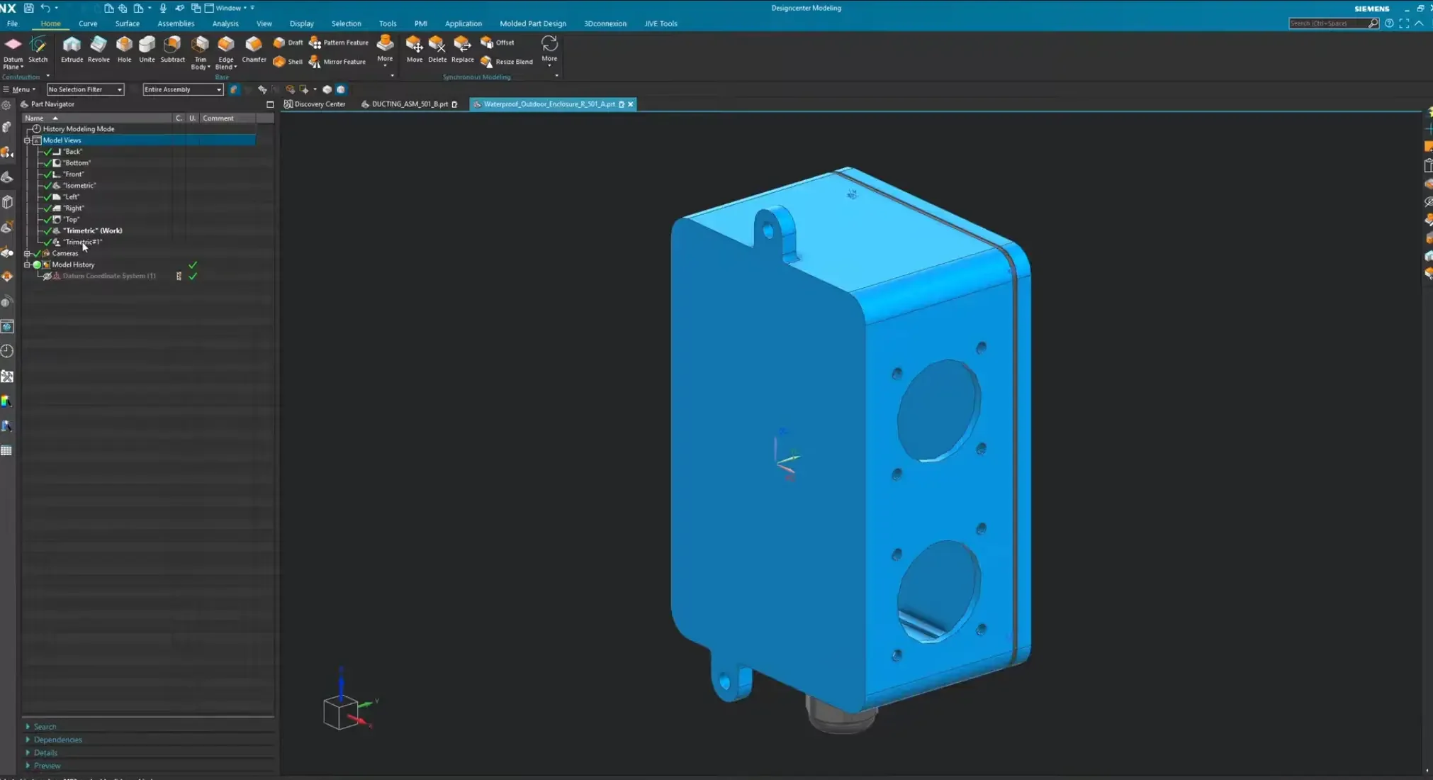
Navigate to the Part Navigator tab on the left sidebar.
Expand the Model Views dropdown node to see the standard defaults (Top, Isometric, Trimetric, etc.).
Right-click your preferred baseline view—the Trimetric view works phenomenally well for this layout—and select Copy.
Right-click the root Model Views folder parent node and select Paste.
Rename the newly generated node (Trimetric_1) to explosion.
Double-click the explosion view node. The screen will flash briefly, indicating it is now your active work view environment.
Step 2: Initialize the Assembly Explosion Command
With your view workspace established, transition to the assembly command tools to begin the translation.
Open the Assemblies ribbon tab at the top of the screen.
Locate the descriptive editing panel and click the Exploded Views command button.
In the resulting dialog configuration panel, click New Explosion. NX will prompt you to initialize a dedicated state matrix.
Step 3: Fast Tracking Layouts via "Auto-Explode All"
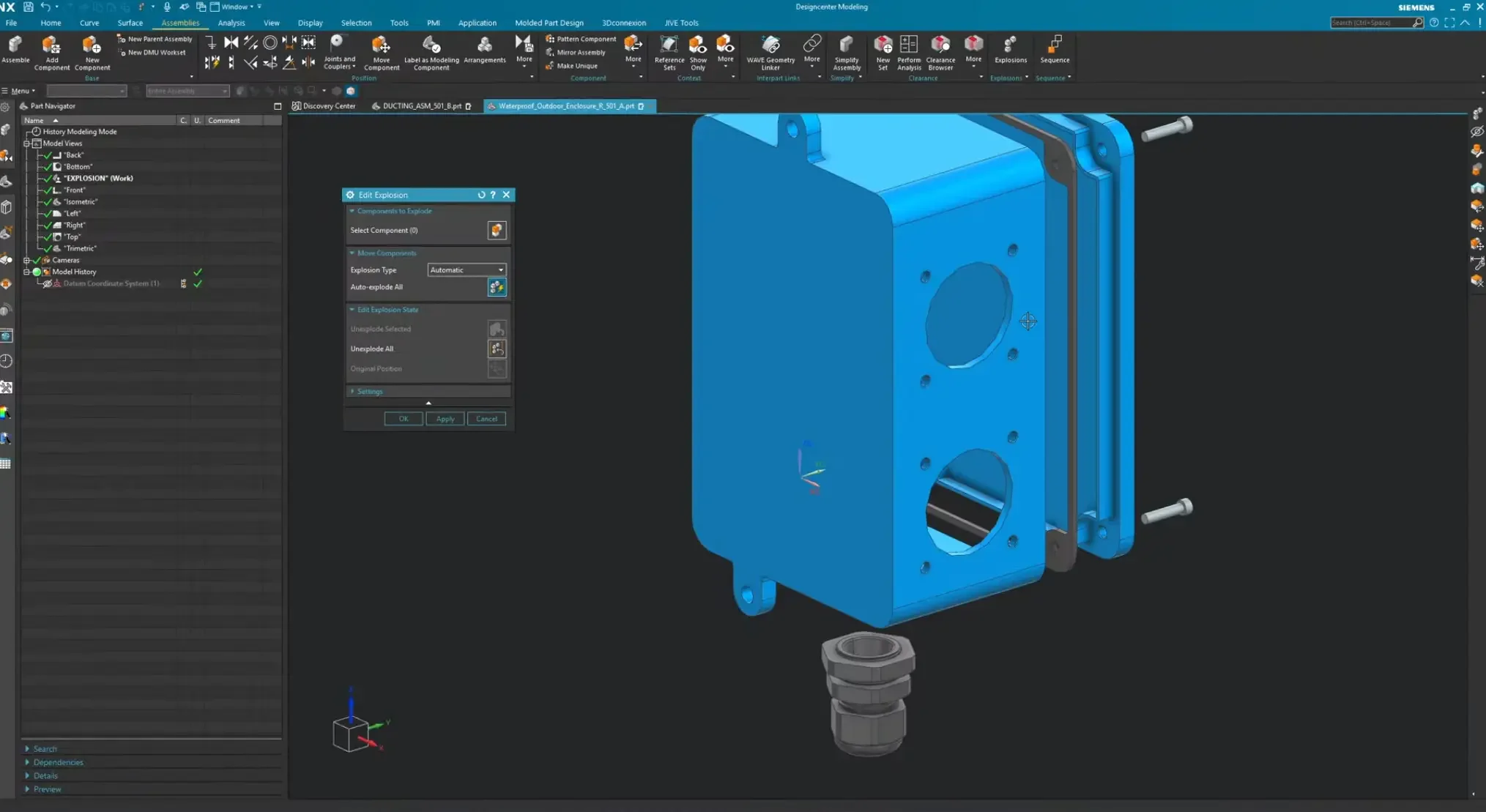
For dense components or standard hardware layouts, moving every single screw manually is an inefficient use of time—as we like to say, we aren't getting paid by the hour here. 1. Within the explosion configuration menu, ensure the type flag is set to Automatic.
1. Click the Auto-Explode All button.
2. Give the system solver a brief moment to calculate the volumetric spacing of your assembly. NX will instantaneously push your parts outward into a clear, concentric blast configuration.
Step 4: Refining Component Clusters Manually
While the automatic solver does a fantastic baseline job, dense sub-components (like a matrix of case screws) frequently require explicit directional fine-tuning.
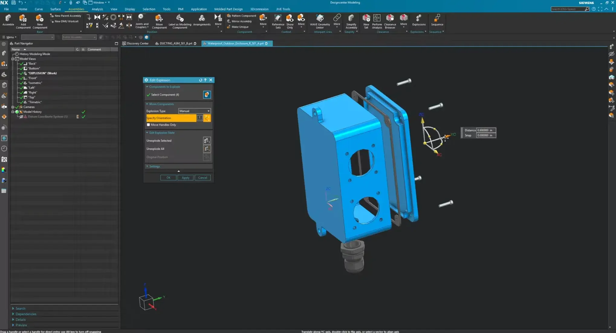
Switch your configuration type selector token from Automatic over to Manual.
Click and drag a selection marquee box around the components you want to move (such as a cluster of four corner fasteners).
Click the Specify Orientation handle toggle to summon the 3D coordinate movement triad.
Left-click and hold your cursor on the desired translation axis vector line (for example, the $YC$ vector stem).
Drag your mouse outward to extend the distance clearance gap smoothly, then click OK to commit the position update.
Step 5: Mapping Path Routing with Associative Trace Lines
On large-scale assembly sheets, visually tracking a component back to its internal thread socket can be challenging. Adding Trace Lines solves this communication gap cleanly.
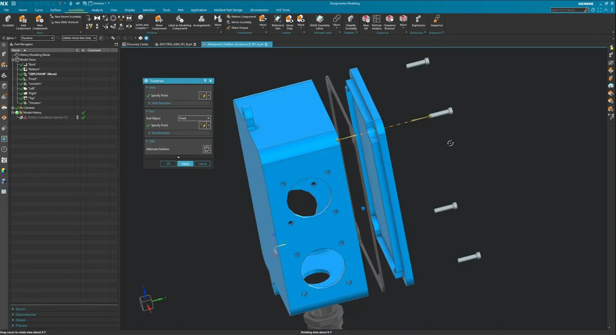
Click the Create Trace Line button inside the exploded views workspace.
Hover your cursor over your displaced component and select an explicit circular reference center point (like the underside rim of a screw shank).
Move your cursor down to the destination assembly part and select the corresponding target hole center.
The Alignment Check: Ensure your directional tracking arrows are pointing toward one another. This allows the background solver to stitch a clean, straight dash-dot track line between the features.
Click Apply to anchor the line. Repeat this sequence one by one for the remaining fastening paths across your housing interface.
Step 6: Toggling Between Spatial View States
Once your trace lines are locked down, close the dialog window. Your documentation assets are fully integrated. Because this whole layout lives completely inside a standalone model view state, you can instantly hop back and forth between design configurations:
To return to standard modeling mode, double-click the default Trimetric node in your Part Navigator. Your assembly instantly telescopes back together, tracking perfectly back to its native unexploded constraints.
To jump back into your documentation display layout, simply double-click your custom explosion node. Your components will seamlessly shift right back out to their designated exploded coordinates, complete with your trace lines displayed.
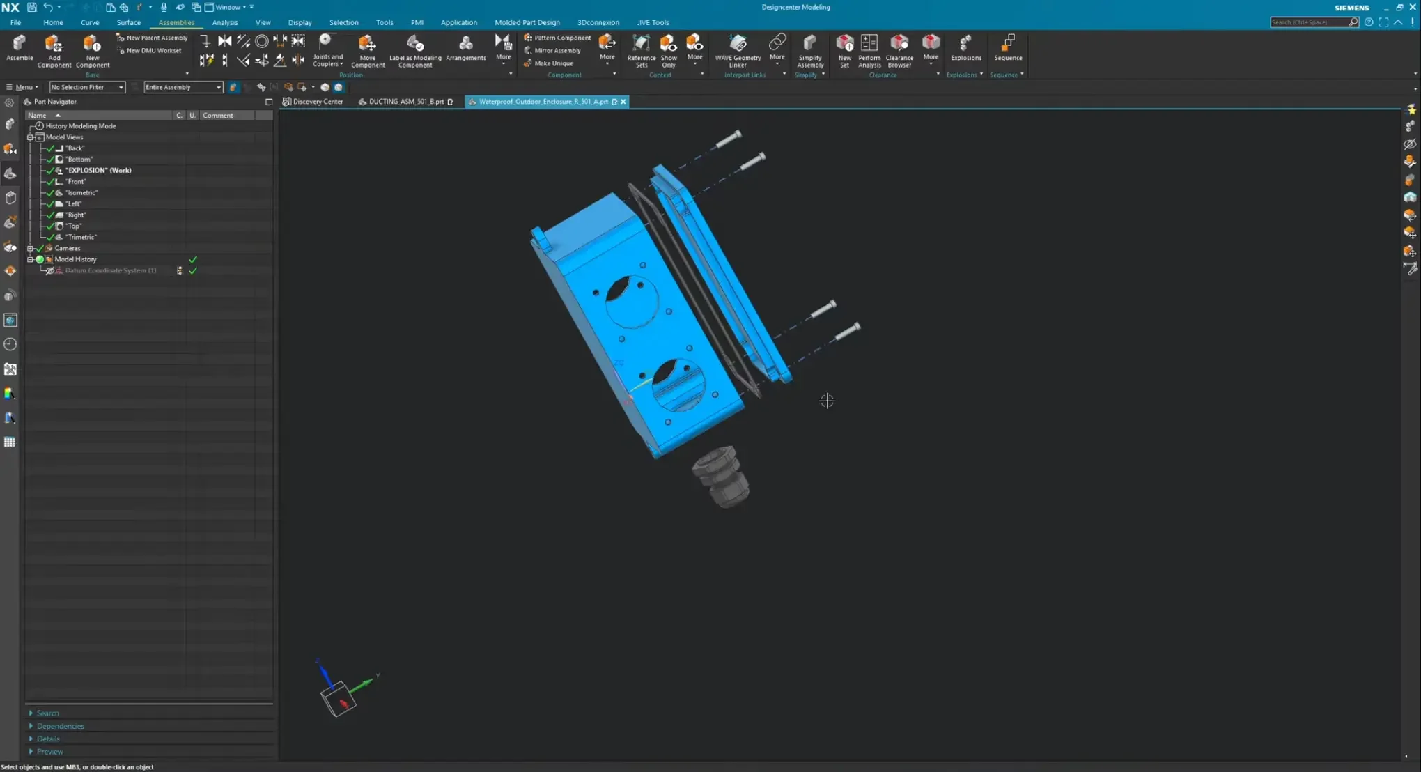
This isolated view technique can now be fed cleanly into an engineering sheet layout drawing template or exported directly into production manufacturing instruction graphics.
Next Steps: Master Assembly Documentation & Design Layouts
Isolating complex component layers is an essential step for flawless technical communication. Take complete control over your assembly architectures and automated layouts with these deep-dive Siemens NX guides:
Automate Component Arrays Across Layouts: Once you know how to explode individual parts out of a layout, learn how to quickly distribute those components in massive arrays using The Pattern Feature in NX: Beyond the Basics.
Drive Top-Down Assembly Hierarchies: Ensure your multi-part models maintain pristine structural integrity before you ever map out explosion states by mastering How to Use the WAVE Geometry Linker for Top-Down Assembly Design.
Scale These Workflows Across Your Engineering Team
Standard software tutorials only go so far when facing unique, real-world production bottlenecks. If your design team is struggling with workflow inefficiencies, modeling errors, or assembly instability, we can help.
At JIVE Engineering, we provide specialized, bespoke Corporate Engineering & CAD Training customized entirely around your company’s native production files and internal design standards. We move your team past basic button-clicking and equip them to build robust, failure-proof modeling workflows that save hours of engineering time.
Explore Our Custom Training Programs or Contact Our Team today to discuss your team's specific training needs.