
How to Use the WAVE Geometry Linker for Top-Down Assembly Design
If you are expanding your skills in Siemens NX, you have likely run into a tool that sits at the absolute core of advanced modeling: the WAVE Geometry Linker.
It’s one of the most powerful features in the software, but because it requires a specific licensing structure and a high degree of organizational discipline, it often intimidates new users.
To break it down as simply as possible: WAVE geometry linking is the backbone of Top-Down Assembly Design.
Watch the video!
Top-Down vs. Bottom-Up Assemblies
To understand why we use the WAVE linker, we first have to contrast the two main assembly methodologies:
Bottom-Up Design (Traditional): This is what most engineers are used to. You design individual components cleanly in their own separate windows (like standard bricks or Legos), bring them into an assembly file, and use geometric constraints to snap them together. The data is pre-defined; you are just managing the positioning. It works, but it can be incredibly slow when making sweeping design changes.
Top-Down Design (Parametric Layout): Imagine someone hands you a 3D model of a boat hull and says, "Design custom storage blocks that sit flush inside this exact curvature." The blocks don't exist yet. Instead of manually measuring the hull, guessing draft angles, and copying dimensions, Top-Down design allows you to build the new components directly around the existing layout geometry. You are borrowing what is already there to drive your new parts.
Let's walk through a foolproof example of this workflow: designing a perfectly flush-fitting lid for a pre-existing drafted cup model.
Step 1: Establish the Assembly Hierarchy
Before linking any geometry, we need to transition our standalone part into an assembly framework.
With your base model open (e.g., cup_wave.prt), navigate to the Assemblies ribbon.
Select New Parent Assembly and name the file (e.g., cup_assembly.prt). NX will automatically nest your cup as a child component.
Rather than adding a pre-built part, click New Component in the top ribbon.
Name this new empty file lid and hit OK.
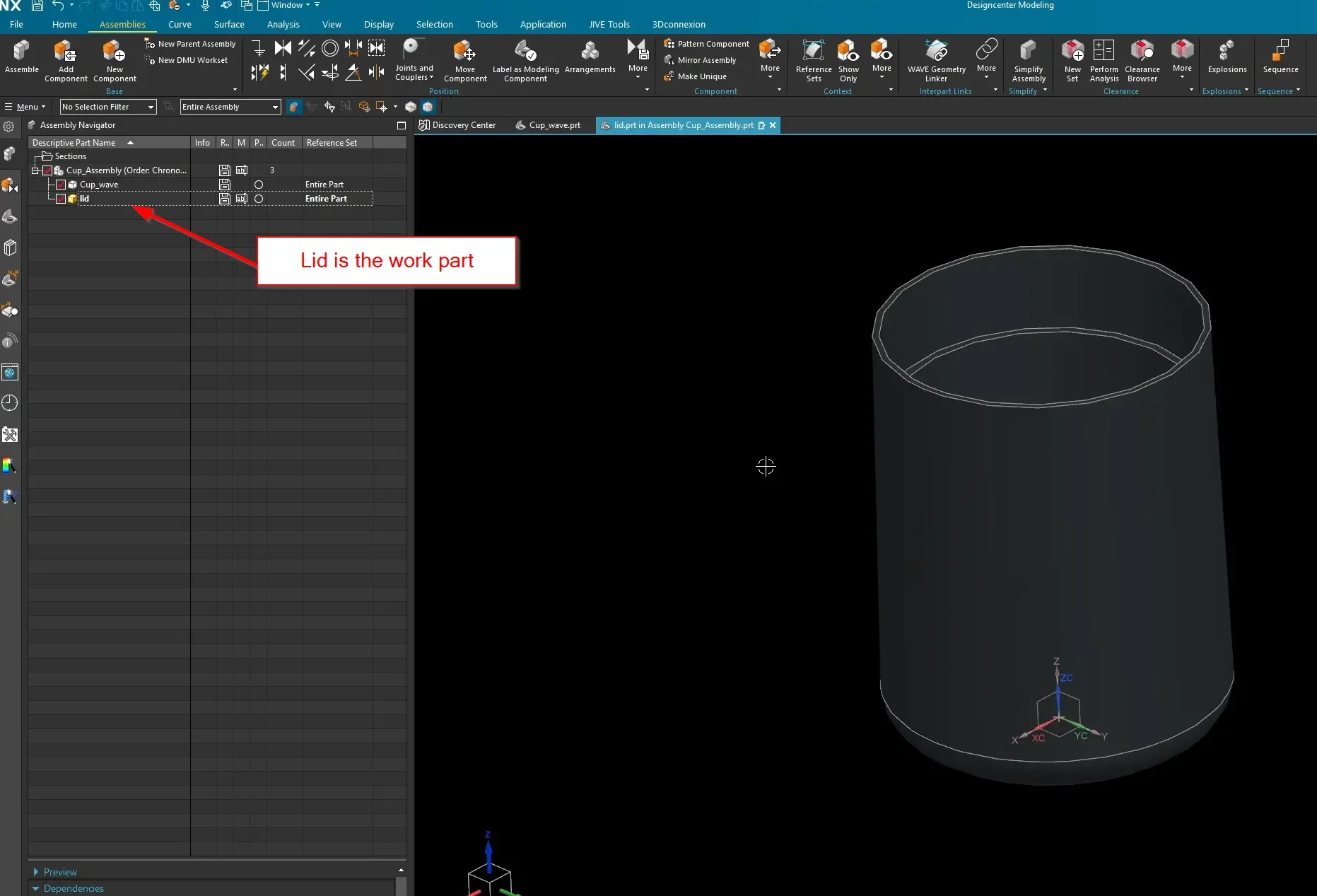
In your Assembly Navigator, double-click on the lid component. This makes it your active Work Part, denoted by a gold box icon next to its name. You can now design inside this file while maintaining full visual context of the surrounding assembly.
Step 2: Launching the WAVE Geometry Linker & The Two Golden Rules
With the lid set as your active work part, go to the Assemblies tab and launch the WAVE Geometry Linker command. (Fun fact: WAVE technically stands for What-If Alternative Variable Engineering).
Before selecting geometry, you must commit these Two Golden Rules of WAVE Linking to memory:
The Law of Associativity: By default, the WAVE linker copies geometry from a parent part to a child part associatively. If the parent geometry changes down the road, the child part automatically updates to match it.
The Law of Position: Because of this associative relationship, the WAVE link copies assembly position data along with the shape. If the parent component moves to a new coordinate space inside the assembly, the child geometry will follow it.
Rule of Thumb: Just because you CAN borrow everything doesn't mean you SHOULD. A clean top-down design requires data minimalism. Always feed parameters from the parent DOWN to the child—never from the child UP.
Step 3: Selecting and Inter-Part Copying the Surfaces
For our lid design, we don't need to link the entire solid body of the cup. We only need the surfaces that the lid will physically touch.
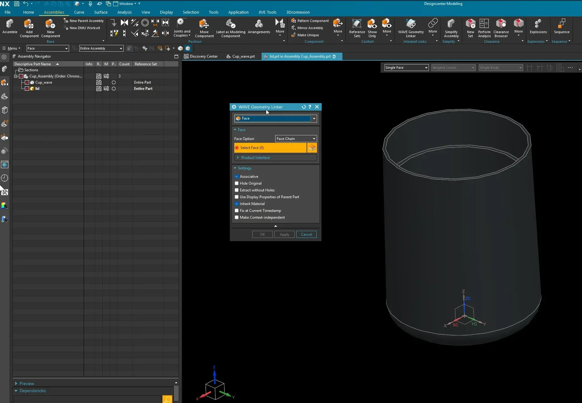
In the WAVE dialog box, set your Selection Type filter to Face.
Change the selection scope to Face Chain so connected surfaces are treated as a single geometric entity.
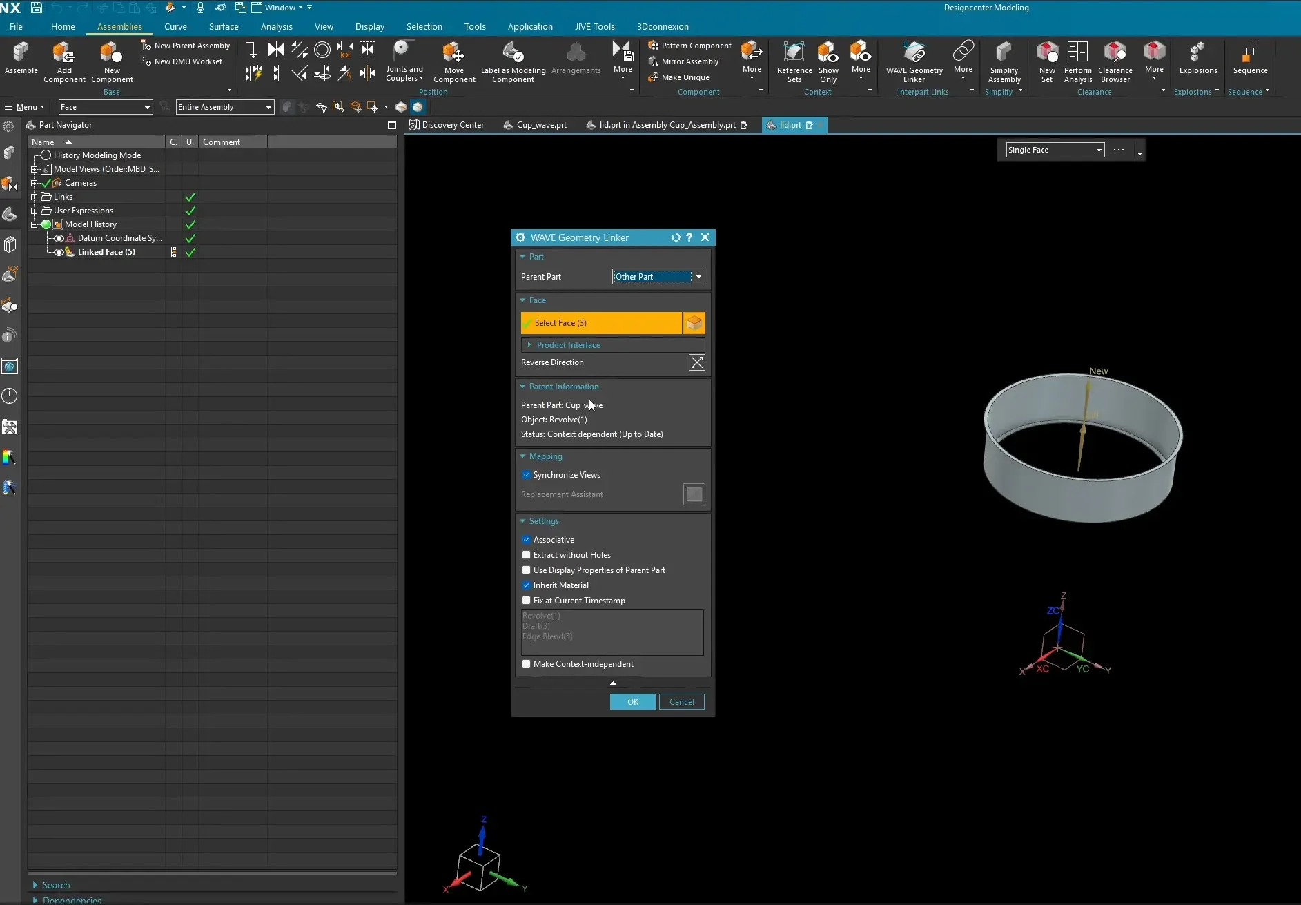
Select the interior lip surface, the vertical drafted face, and the top rim face of the cup.
Ensure the Associative checkbox is turned on in the settings panel, then click OK.
If you open the lid.prt file in a new window, you will see a clean, purple-tinted feature in your Part Navigator labeled Linked Face. Double-clicking this feature will explicitly show you the identity of its parent file.
Step 4: Surfacing the Final Component Data
Now that the master geometric curves are safely copied into the child file, you can build out the solid model using standard modeling tools:
Use Extrude Sheet or a Bounded Plane to seal the top of the linked surface boundaries.
Launch the Sew command to combine your new sheets with the linked WAVE faces. NX will automatically stitch the surfaces into a closed, watertight Solid Body.
Adding Clearance: If you take an assembly section view (Ctrl+H), your parts will be touching with zero tolerance. To fix this cleanly, keep the lid as your active work part, launch the Offset Face tool, and apply a global clearance offset (e.g., 0.25mm or 10 thou) to the interior linked faces.
Testing the Parametric Logic
To prove that your top-down design behaves correctly, you can intentionally stress-test the model against both Golden Rules:
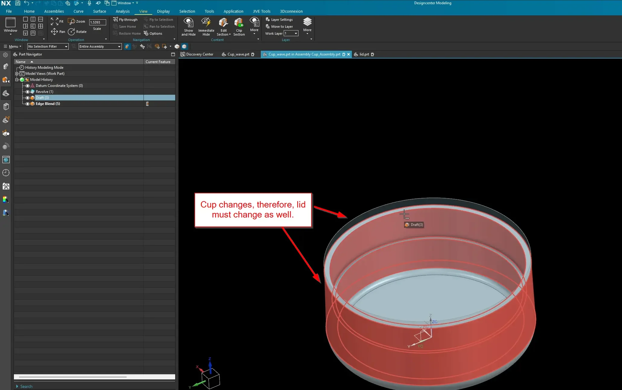
Testing Rule 1 (Geometry): Open the original master cup file independently, open its base sketch or revolve feature, and alter the height or top diameter. When you return to the assembly window, you will watch the lid instantly resize and shift its walls to maintain its perfect, offset fit.
Testing Rule 2 (Position): Use the Move Component command on the master cup. As the cup translates through 3D space, the unconstrained lid will dynamically stick to it like glue.
(Note: If you attempt to use the Move tool directly on the child lid part inside the assembly, it will stubbornly snap back to its parent alignment space, honoring the master position link.)
By mastering this baseline surface-linking method, you can cleanly apply Top-Down automation to complex cast interfaces, wiring harness pathways, and interlocking housing splits across your entire project catalog.
Next Steps: Secure Interpart Geometry & Automate Frameworks
Mastering associative interpart relationships is the foundation of high-level assembly control. Continue building stable, scalable top-down architectures with these advanced Siemens NX workflows:
Isolate and Clean Up Your Interpart Links: Stop creating messy, direct-geometry links that corrupt over time. Learn how to publish an intentional reference layer between your parts using our guide on the Product Interface Command in Siemens NX.
Drive Entire Structural Layouts Top-Down: Put your skeleton-sketch WAVE link workflows to work by automatically scaling massive industrial frame structures using our Structure Designer Tutorial in Siemens NX.
Scale These Workflows Across Your Engineering Team
Standard software tutorials only go so far when facing unique, real-world production bottlenecks. If your design team is struggling with workflow inefficiencies, modeling errors, or assembly instability, we can help.
At JIVE Engineering, we provide specialized, bespoke Corporate Engineering & CAD Training customized entirely around your company’s native production files and internal design standards. We move your team past basic button-clicking and equip them to build robust, failure-proof modeling workflows that save hours of engineering time.
Explore Our Custom Training Programs or Contact Our Team today to discuss your team's specific training needs.