
Migrating to Siemens NX 2506: 5 Essential New Sketcher Interface & Workflow Fixes
If you are currently migrating your system setup to the Siemens NX 2506 Continuous Release from a legacy version like NX 12 or NX 2212, your first encounter with the new Sketcher solver engine might feel a little jarring.
Let's not sugarcoat it: for traditional "OG" NX users, the new solver logic has a steep learning curve. But once you uncover a few hidden environment toggles, hidden workflow benefits, and CAD administration hacks, the system becomes incredibly fast, predictable, and stable.
Whether you are a long-time NX developer or a legacy PTC Creo user transitioning into an NX environment, here are 5 critical tips to optimize your NX 2506 Sketcher workflow.
Watch the Video!
1. Goodbye Profile Tool: Navigating the New Line Tool Logic
The first major shock when entering a sketch in NX 2506 is the structural removal of the legacy Profile tool. It’s a tool many of us used heavily, but Siemens has shifted the layout.
Now, continuous line string creation is fully handled by the updated Line tool. When you finish a chain sequence, you simply right-click or use the on-screen context menu to select Break Chain.
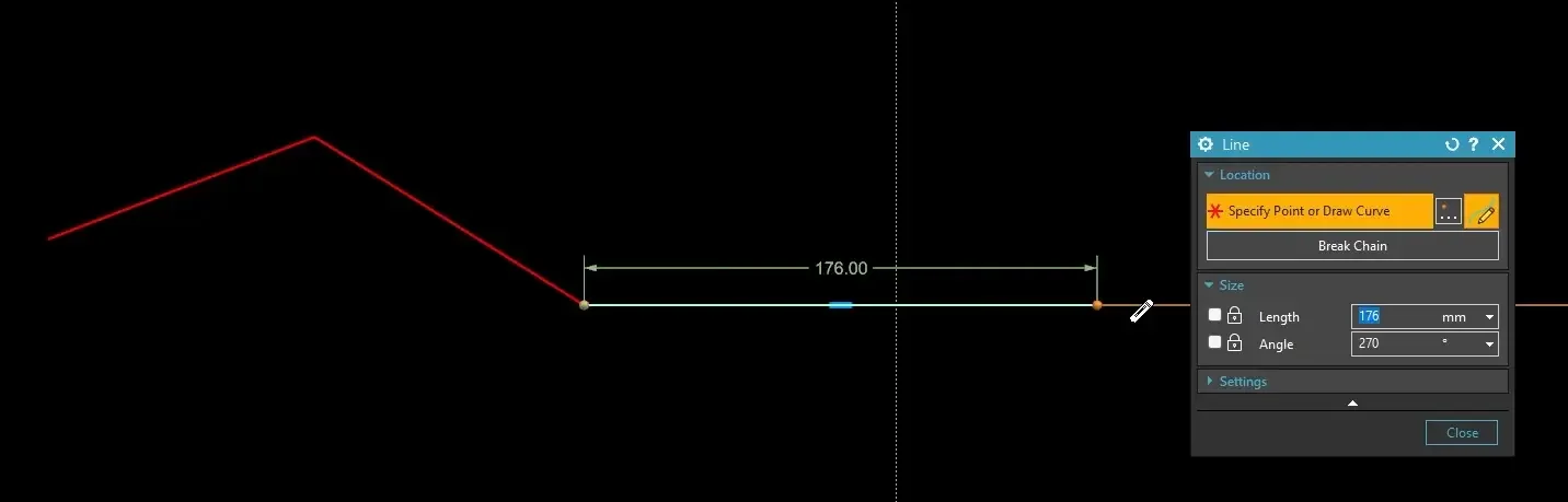
Furthermore, the old method of seamlessly switching from a line to a tangent arc within the same profile command is gone. You must now explicitly drop the line command and execute the standalone Arc tool to round out your corners. It’s an adjustment, but it brings NX much closer to the streamlined line-chain mechanics found in modern parametric packages.
2. Construction Geometry Built In: Create Reference Geometry Toggles
For years, creating construction geometry in NX meant sketchers had to draw a standard line, click the curve, and manually select "Convert to Reference." In NX 2506, we finally have a native shortcut.
Inside the settings panel of the Line, Arc, and Rectangle tools, you can now toggle on Create Reference Geometry.
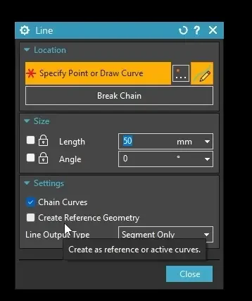
When active, every line or boundary box you draw immediately renders as dashed reference geometry. This allows you to rapidly build skeletons and dimension attachment curves without generating solid objects that throw errors during an Extrude or Revolve operation.
(Note: This flag applies to lines, arcs, and rectangles, but is notably missing from the Spline command, which still requires manual conversion.)
3. The Power User Holy Grail: Infinite Lines & Centerlines
If you come from a Creo background, you are likely used to slapping down centerlines constantly to drive symmetrical layouts and helical profiles. Historically, NX didn’t support this natively; you had to draw a loose segment, extend it, and turn it into a reference.

NX 2506 introduces an Infinite Line Only setting directly inside the Line command properties. By combining this flag with reference geometry, you instantly gain an infinite parametric centerline. This is an absolute game-changer for anchoring symmetrical constraints or establishing clean rotation boundaries for complex threaded cuts and helical sweeps.
4. Driving MBD/PMI with "Convert to Half Diameter"
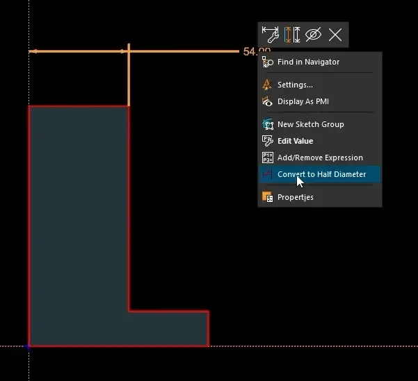
When revolving geometry around an infinite centerline, sketching in radial values can lead to tedious downstream drawing math. NX allows you to easily transform a radial dimension into a true diameter dimension.
Select your centerline/axis and your outer sketch curve.
Right-click the automatically generated dimension string.
Select Convert to Half Diameter (a slightly counterintuitive name, as it actually displays the full part diameter).
The Hidden Model-Based Definition (MBD) Benefit
At JIVE Engineering, we focus heavily on Model-Based Definition. We want the exact dimensions driving our 2D sketches to seamlessly populate our 3D production models without manually placing loose annotation parameters.
Because you converted these to diameter dimensions natively in the sketch solver, you can enter the PMI Application, right-click the sketch node in your Part Navigator, select Show Dimensions, and click Display as PMI. Your diameter dimensions will instantly transition to clean, fully associative, model-driven production data.
5. Stop Factoring Constraints Manually: Activate Mechanism Mode
By default, the new Sketcher relies heavily on "found relations" (non-persistent constraints like vertical or horizontal rules). These relations are dynamic and "sticky" until a downstream dimension or push-pull move breaks them.
If you want absolute control and want your constraints hard-coded so they never move or warp when dragged, you don't have to assign dozens of persistent constraints manually. Instead, look for Mechanism Mode in your Sketch settings.
Turn on Mechanism Mode.
NX will immediately ask: "Do you want to infer persistent relations from the current state of the sketch?"
Click Yes.
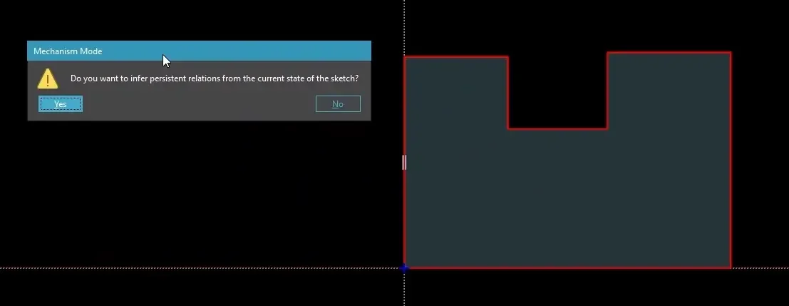
The solver will instantaneously analyze the current state of your sketch lines and convert every single non-persistent relationship into a locked, persistent constraint (collinear, perpendicular, vertical, etc.) automatically. It saves massive amounts of design time and gives you the rock-solid sketch stability found in classic CAD packages.
💡 Bonus CAD Admin Tip: Text Scaling Shortcut
If you are taking screenshots for design reviews or running a high-res 4K monitor on a compact engineering laptop, the default font scaling can make dimensions nearly impossible to read.
To instantly scale up your user interface text on the fly, simply hold the Ctrl key and press the Up Arrow (Ctrl + 🡡). To scale it back down, use Ctrl and the Down Arrow (Ctrl + 🡣).
Next Steps: Master the New Sketch Solver & History Tree Stability
Adapting to interface updates is only the first step toward high-velocity modeling. Lock in your modeling accuracy and protect your history configurations with these specialized NX guides:
Deep-Dive into Modern Constraint Logic: Transition smoothly into the new interface and learn how to manage geometric relations without over-constraining files using our complete list of NX 2506 Sketcher Tips.
Protect Your Parametric Models from Breaking: Learn how to isolate stable sketch features and prevent upstream updates from breaking your part architecture down the line by discovering What is Fix at Current Timestamp and how does it work?.
Scale These Workflows Across Your Engineering Team
Standard software tutorials only go so far when facing unique, real-world production bottlenecks. If your design team is struggling with workflow inefficiencies, modeling errors, or assembly instability, we can help.
At JIVE Engineering, we provide specialized, bespoke Corporate Engineering & CAD Training customized entirely around your company’s native production files and internal design standards. We move your team past basic button-clicking and equip them to build robust, failure-proof modeling workflows that save hours of engineering time.
Explore Our Custom Training Programs or Contact Our Team today to discuss your team's specific training needs.