
Siemens NX Arrangements vs. Reference Sets: What is the Difference?
Watch the Video!
Need a video to help you through this process? Then check out the video on YouTube!
If you’ve spent any time in Siemens NX, you’ve likely encountered both Reference Sets and Arrangements. On the surface, they seem to do the same thing—control what you see on your screen. However, using the wrong one can lead to a messy assembly navigator and a lot of frustration.
In our latest tutorial, we break down the fundamental differences between these two powerful tools and show you exactly when to use each to keep your CAD models clean and efficient.
The Main Difference: Part Level vs. Assembly Level
The easiest way to remember the difference is to think about where the control lives:

- Reference Sets are defined at the Part level. While you can use this for assemblies, it is not recommended. Below is an explanation from two sources on why.
A little history on where reference sets came from may help.
Back in the old days of UG2, preV10, reference sets were used in component parts to filter out the miscellaneous objects of the data base so when you created a cube, you would only bring to your assembly the 12 lines used to represent the cube. At that time, the drawing was ususally done in the same file as the geometry so the reference set would exclude all drafting stuff. You would still need reference sets of assemblies to capture only the geometry for the next higher level.
Move up to V10+ with solids and you would have your skecth entities that would be excluded from the reference set. You only wanted the solid model in the ref set to move up to the assembly. Using a ref set at the assembly was considered not necessary with the drafting now in a separate file, if using the master model technique.
After about V16, the programmers got smart enough to leave the sketch geometry behind automatically when you used the 'entire part' ref set in your assembly. They also added an automatic MODEL (or was it SOLID, settable in customer defaults?) reference set to your files that contained the solid body when you created a part. It would update automatically as you worked on the solid.
That should help you understand where reference sets came from and their intended use.
- looslib, Eng Tips
Where problems can occur is when the Component that you add to the Reference Set is an Assembly itself, particularly if there are sub-assemblies in it. Only the Components that you explicitly select will be included in the Reference Set but if later on some additional Components are added to one of those sub-Assemblies, they will not show-up at the level that that Reference Set is used when the Component was added to the top-level Assembly.
- JohnRBaker, Eng Tips
- Arrangements are defined at the Assembly level.

1. Reference Sets: What is inside the part?
Think of a Reference Set as a "filter" for the geometry within a single part file. When you bring a part into an assembly, you don't always want to see every datum plane, sketch, or construction surface.
- In vanilla NX, there are 3 default reference sets. You can see them below.
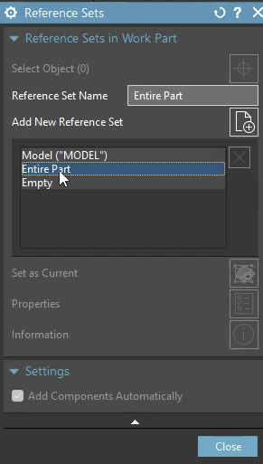
- Model - Shows you the 3D model only at the assembly level. Anything that is not a body is omitted. Sometimes also called Solid.
- Entire Part - Shows you the whole part and its entities at the assembly level. Can be catastrophic if there is a lot of data such as sketches, points, etc. Useful for skeleton models.
- Empty - Shows you nothing at the assembly level. Used for large assembly management.
- Custom Reference Sets - You can create your own reference sets if these do not satisfy what you are looking for.
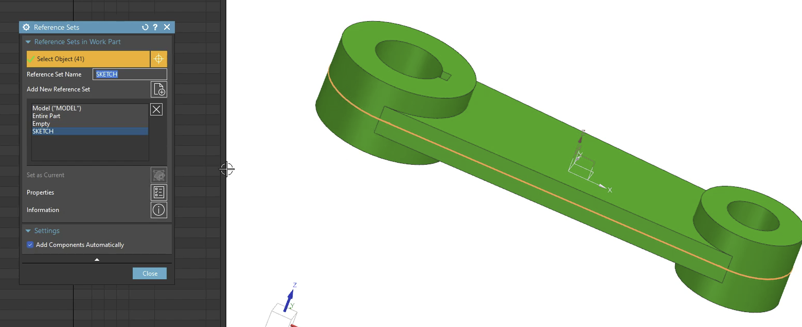
In this case, we made a reference set called Sketch and included the actual sketch in it. Even though it is one feature, it has 41 objects in it.
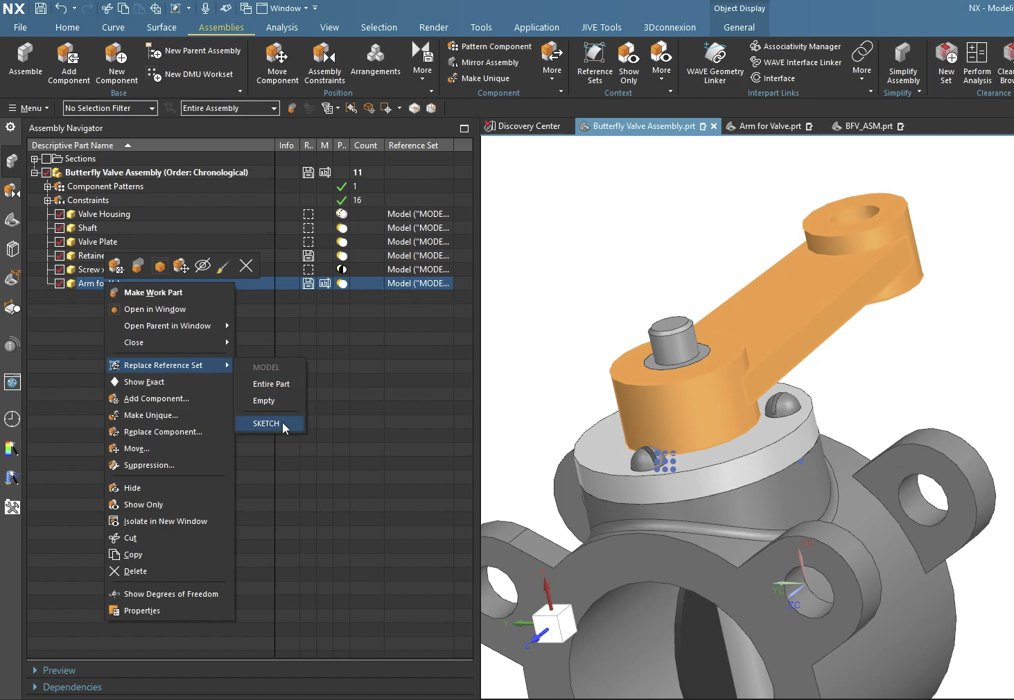
Going back to the assembly, you can change the reference set by right clicking on the component and selecting the appropriate reference set.
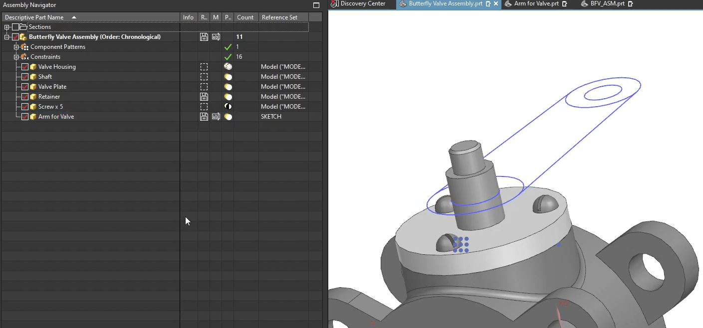
This is what it looks like when the reference set is replaced.
2. Arrangements: Where are the parts located? Do they need to be displayed?
Arrangements are designed to handle different "states" of an assembly. If you have a butterfly valve that needs to be shown in both an "Open" and "Closed" position, you don’t need two separate assembly files—you need two Arrangements.
In addition, arrangements can assist you in large assembly management. You can use them to control what items are displayed. If a certain component takes very long to load, you can use arrangements to suppress it and stop it from loading. Granted, certain relationships will be temporarily broken, but once the item is un-supressed, those relationships are re-established.
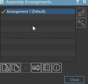
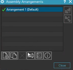
- In vanilla NX, there is only 1 default arrangement. This arrangement is simply a placeholder, it doesn't actually do anything.
Creating an Arrangement to Suppress Items
As stated, you can use arrangements to remove items from display in an assembly. You will find this incredibly useful with large assemblies, as you can use the concept is Assembly Load Options to only open what is un-suppressed.
Step 1: Define a New Arrangement
The first things you must do is define a new arrangement. Make sure to give this a name that makes sense, and that everyone can use. Remember, sometimes, you are working with a team!
- Create a new arrangement.
- Make it the active arrangement. You can do this by double clicking on your new arrangement.
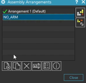
Step 2: Suppress the Items
The next step is to go through the list of items you want to suppress.
- Select the component you wish to suppress, and right click on it. Select Suppression…
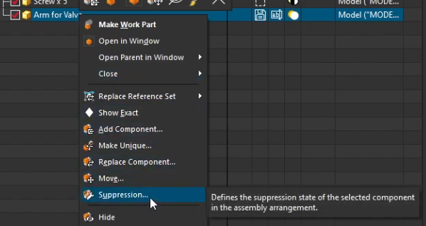
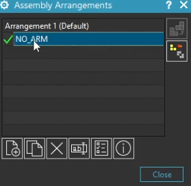
2. The following window comes up. You must now select what happens to this component in what arrangement. We want to Always Suppress the component in the NO_ARM arrangement**.**
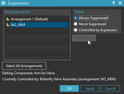
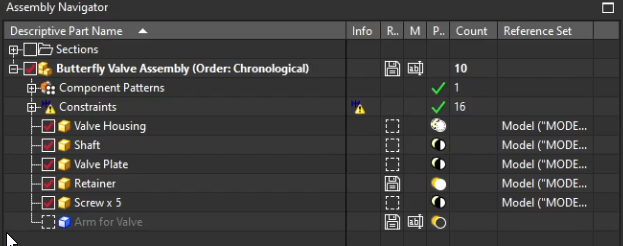
3. Confirm the configuration. Your tree should show the arm suppressed, represented by a blue block.
Creating an Arrangement for Position Purposes
Arrangements allow you to define different states of an assembly within a single file. You can control component positions, suppress or unsuppress parts, and change constraint values (like distance or angle) specific to each arrangement.
Step 1: Open the Assembly Arrangements Dialog
First, you need to access the Arrangements command.
- Go to the Assemblies tab on your ribbon.
- Click it. Open the Arrangements dialog box.
Step 2: Create Your New Arrangements
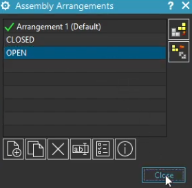
Now, let's define the different states you want to capture (e.g., "Open" and "Closed").
- In the dialog box, click New Arrangement.
- Rename the new arrangement to something descriptive, like
Open. - Create another one for the closed valve (e.g.,
Closed). - Activate the arrangement you want to work on by double-clicking it. The active arrangement will have a checkmark next to it.
Step 3: Make Constraints "Arrangement Specific"
This is the most critical step. By default, constraints apply globally. You need to tell NX that this specific constraint should change based on the arrangement.
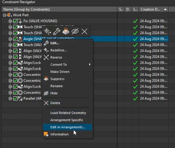
- Open your Constraint Navigator.
- Find the constraint that controls the movement (e.g., a "Distance" or "Angle" constraint).
- Right-click on that constraint.
- Select Edit in Arrangements.
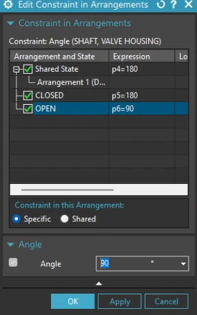
Step 4: Edit the Constraint Value
Now that the constraint is tied to the active arrangement, you can change its value.
- Be sure to set each arrangement that must house a different configuration to Specific.
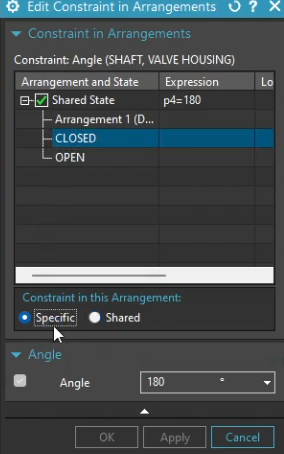
- For closed, set the value to
180, while for open set it to90.
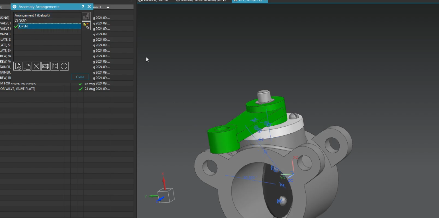
- Switch to your "Open" arrangement by double-clicking it in the Arrangements dialog. You should see the valve open!
Summary
Arrangements are a powerful way to keep your assembly file clean while documenting all necessary range-of-motion states. They are incredibly useful for drafting views, where you can place one view in the "Open" state and another in the "Closed" state from the same file. In addition, you can use them to control massive assemblies that can take a very long time to load!
Reference sets, however, should be best reserved for parts. They are useful for filtering things out of the assembly, so your assembly can show all parts in a neat and organized way. That is not to say that is is not allowed to use them in assemblies; we have certainly seen companies do that! After all, if it wasn't allowed, Siemens would not let you do it! However, we leave that level of curiosity to you!
Next Steps: Advance Your Assembly Management
Now that you know how to use Reference Sets for individual parts and Arrangements for moving assemblies, continue optimizing your top-down modeling workflow with our technical guides:
Accelerate Component Placement: Learn how to rapidly snap parts into your layouts using our guide on How to Use the Siemens NX Assemble Command.
Control Top-Down Geometry: Discover how to create stable inter-part relationships across assemblies with our tutorial on Using the Siemens NX WAVE Geometry Linker.
Standard software tutorials only go so far when facing unique, real-world production bottlenecks. If your design team is struggling with workflow inefficiencies, modeling errors, or assembly instability, we can help.
At JIVE Engineering, we provide on-site Siemens NX Corporate Training customized entirely around your company's actual production files, native geometry, and internal workflows. We help your design team transition from basic button-clicking to mastering robust, failure-proof top-down modeling strategies.
Explore Our Custom NX Training Programs or Contact Our Team today to schedule a workflow audit.