How to Use the Measure Tool in Creo Parametric
In the fast-paced world of 3D modeling, you need to verify dimensions quickly without digging through the model tree. The Measure Tool in Creo 10 is one of the most frequently used features, yet many users only scratch the surface of what it can do. Whether you're checking clearance for an assembly or verifying the surface area for a coating, getting the right data fast is key.
In our latest video tutorial, we dive deep into the modern Measure interface in Creo 10. Watch the video below to see the tool in action, then check out our "Quick-Reference" guide below.
Watch the video!
The Power of the Measure Summary Tool
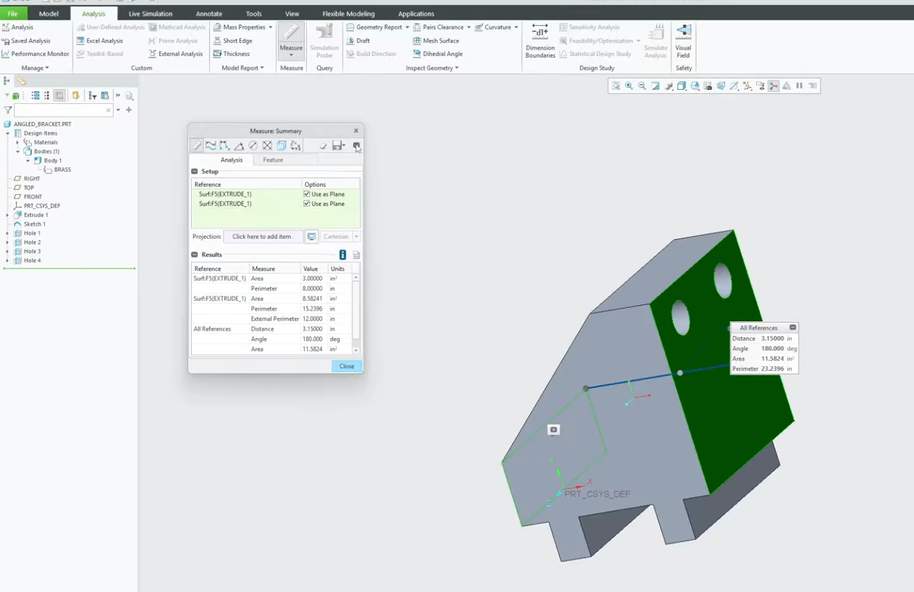
One of the best updates in recent versions of Creo is the Summary mode. Instead of picking a specific tool for "Distance" or "Diameter," you can simply select your geometry, and Creo will intelligently provide the most relevant data.
Select a Single Edge: Get the length.
Select a Circular Surface: Get the diameter and area.
Select Two Parallel Planes: Get the distance between them.
Step-by-Step: Measuring Like a Pro
Open the Tool: Navigate to the Analysis tab and select Measure.
Select Your References: Click your first point or surface. Hold the CTRL key to select your second reference.
Check the Results Panel: Look at the floating panel for the primary measurement, or expand the Results Table for a detailed breakdown (including X, Y, and Z offsets).
Change Units on the Fly: Need to see the result in millimeters instead of inches? Use the Units drop-down directly within the measure dialog without changing your entire model's settings.

3 "Power User" Tips for Creo 10
Save as Feature: Did you know you can save a measurement as a feature in your Model Tree? This is incredibly useful if you need that dimension to update live as you modify your geometry.
Projection Measurements: Use the "Projection" collector to measure distance along a specific axis or relative to a specific coordinate system.
The "Ctrl" Shortcut: You can often bypass the menu entirely by selecting two items while holding CTRL, then right-clicking to see basic measurement data.
Next Steps: Advance Your Assembly Analysis & Coordinate Controls
Measuring simple physical clearances is just the entry point to digital product validation. Take full control of your assembly physics and external data points with these essential Creo guides:
Analyze Weights and Balances: Move past basic linear dimensions and calculate exact component weights, volumes, and geometric balance points using our guide on Finding Mass Properties and Center of Gravity in Creo Parametric.
Import External Inspection Coordinates: Learn how to pull precise data-point coordinate files into your model from CMM logs or Excel lists to compare them against live measurements with How to Import Point Files in Creo Parametric.
Scale These Workflows Across Your Engineering Team
Standard software tutorials only go so far when facing unique, real-world production bottlenecks. If your design team is struggling with workflow inefficiencies, modeling errors, or assembly instability, we can help.
At JIVE Engineering, we provide specialized, bespoke Corporate Engineering & CAD Training customized entirely around your company’s native production files and internal design standards. We move your team past basic button-clicking and equip them to build robust, failure-proof modeling workflows that save hours of engineering time.
Explore Our Custom Training Programs or Contact Our Team today to discuss your team's specific training needs.