Finding Mass Properties and Center of Gravity in Creo Parametric: A Step-by-Step Guide
Intro: Whether you are designing for consumer electronics or heavy industrial machinery, understanding your model’s mass properties is a critical step in the engineering process. In PTC Creo Parametric 10, the tools for calculating weight, volume, and the Center of Gravity (COG) are more intuitive than ever—but only if you know where to look.
In our latest video tutorial, we break down the exact workflow to ensure your engineering data is accurate. Watch the video below, or follow our written guide for a quick refresher!
Why Mass Properties Matter
In the world of CAD, your model is more than just a 3D shape. It’s a physical object. Finding the Center of Gravity (CG) is essential for:
Balance & Stability: Ensuring a product won’t tip over.
Shipping & Logistics: Knowing the exact weight for freight costs.
Structural Analysis: Correctly applying loads in FEA (Finite Element Analysis).
Step 1: Assigning Material Properties
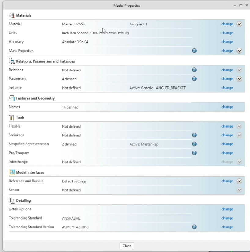
You can't get an accurate mass without a density. Before running an analysis, ensure you have assigned a material to your part or assembly.
Go to File > Prepare > Model Properties.
Click Change next to Materials.
Choose from the standard Creo library (e.g., Steel, Aluminum, Plastic) and click Assign.
Step 2: Running the Mass Properties Analysis
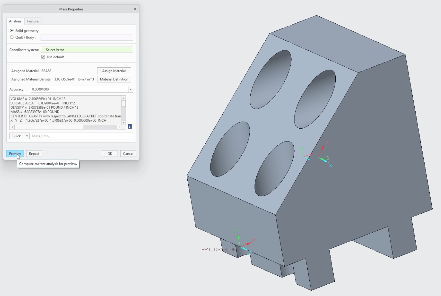
Once your material is set, navigating to the data is simple:
Select the Analysis tab in the top ribbon.
Click on Mass Properties.
In the dialog box that opens, click Preview to see the results instantly.
Step 3: Locating the Center of Gravity (COG)
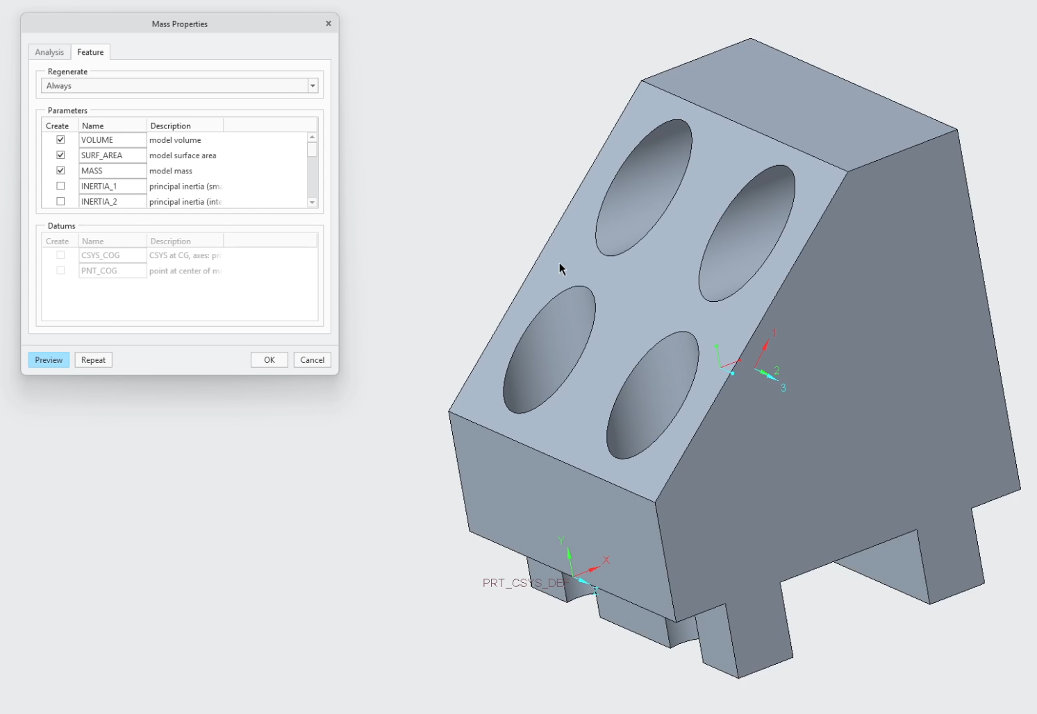
One of the most common questions we get is: "How do I see the CG icon?" In the Mass Properties window, Creo will generate a coordinate system at the balance point of your model. You can also create a Feature from this analysis so that the CG point stays visible and updates automatically if you change the geometry of your part.
Next Steps: Deepen Assembly Validation & Top-Down Physics
Analyzing weight distribution is a critical phase of physical product engineering. Ensure your clearances are exact and manage the skeleton geometry driving your assembly masses with these technical Creo guides:
Verify Clearance and Spacing Volumes: Before finalizing your mass calculations, ensure your physical clearances and component interfaces are spot-on using How to Use the Measure Tool in Creo Parametric.
Control Geometry Driving Your Mass Profiles: Master the top-down workflows that dictate where material is placed across your model by exploring How to Use Publish and Copy Geometry in Creo Parametric.
Scale These Workflows Across Your Engineering Team
Standard software tutorials only go so far when facing unique, real-world production bottlenecks. If your design team is struggling with workflow inefficiencies, modeling errors, or assembly instability, we can help.
At JIVE Engineering, we provide specialized, bespoke Corporate Engineering & CAD Training customized entirely around your company’s native production files and internal design standards. We move your team past basic button-clicking and equip them to build robust, failure-proof modeling workflows that save hours of engineering time.
Explore Our Custom Training Programs or Contact Our Team today to discuss your team's specific training needs.