How to Use Publish and Copy Geometry in Creo Parametric
Watch the Video!
Need a video to help you through this process? Then check out the video on youtube!
In complex assembly design, "Top-Down Design" is the gold standard. It allows you to control the shape and size of multiple parts from a single master skeleton or source part. But how do you pass that information between files without creating a "circular reference" nightmare?
The answer lies in two of Creo’s most powerful data-sharing tools: Publish Geometry and Copy Geometry.
In our latest tutorial, we break down exactly how to use these features to create robust, associative models in Creo 5.0.
1. The "Push": What is Publish Geometry?
Think of Publish Geometry as a "package" or a "folder" you create inside a source part. Instead of another designer having to hunt through your model tree to find the right surfaces or datum planes, you "publish" exactly what they need.
Why use it?
Organization: You can group specific surfaces, chains of edges, and datums into one named feature.
Security & Stability: It acts as an interface. If you change the internal geometry of the part but keep the "Published" interface the same, the downstream parts won't break.
Intent: It tells other team members, "This is the geometry you are allowed to reference."
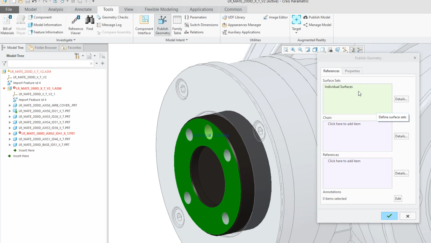
In the image below, we are using Publish Geometry to push the face of the robot that will mate with the end effector we design.
2. The "Pull": What is Copy Geometry?
If Publish Geometry is the "Push," Copy Geometry is the "Pull." This is the feature you create in the target part to bring that published information in.
Key Benefits:
Associativity: When the master part changes, your local "Copy Geom" updates automatically.
Lightweight Assemblies: You don't need to have the entire master assembly open to work on your specific part; you only need the copied references.
Control: You can choose to "un-link" or "freeze" the copy geometry if you want to prevent accidental updates during a specific design phase.
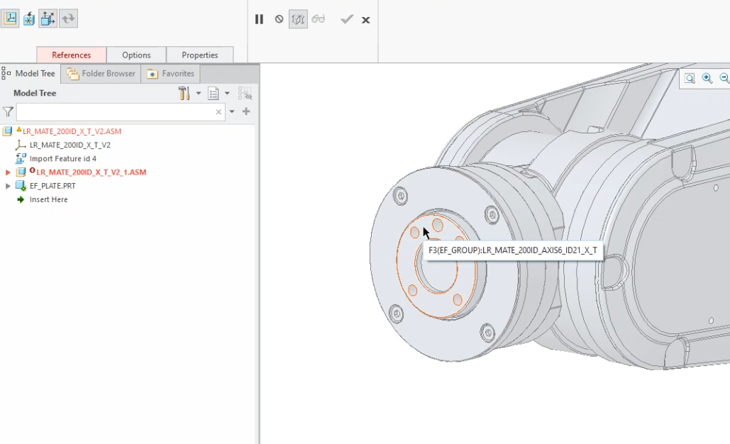
In the image below, the EF_PLATE.prt is using Copy Geometry to receive that face that we published earlier.
The Professional Workflow
In the video, we demonstrate the industry-standard workflow for Top-Down Design:
Identify the critical interface logic in your Skeleton or Master part.
Publish those specific surfaces and datums.
Open your empty component part.
Copy the published geometry from the master into your new part.
Build your solid features using that copied geometry as your primary reference.
By following this method, you ensure that if the master skeleton moves by any amount, every single part in your assembly follows suit—perfectly.
Next Steps: Secure Advanced Assemblies & Analyze Weight Profiles
Isolating your geometric interfaces is the secret to building failure-proof, top-down models. Take full command of your assembly architecture and calculate physical validation properties with these technical Creo guides:
Deploy Your Published Geometry Links: Learn how to consume your newly packaged references downstream to build highly stable interpart features using How To Use Copy Geometry in an Assembly in Creo Parametric.
Calculate Assembly Mass and Balance: Once your top-down bones drive your geometry cleanly, track how your layout choices affect structural balancing with our guide on Finding Mass Properties and Center of Gravity in Creo Parametric.
Scale These Workflows Across Your Engineering Team
Standard software tutorials only go so far when facing unique, real-world production bottlenecks. If your design team is struggling with workflow inefficiencies, modeling errors, or assembly instability, we can help.
At JIVE Engineering, we provide specialized, bespoke Corporate Engineering & CAD Training customized entirely around your company’s native production files and internal design standards. We move your team past basic button-clicking and equip them to build robust, failure-proof modeling workflows that save hours of engineering time.
Explore Our Custom Training Programs or Contact Our Team today to discuss your team's specific training needs.