Fix Your Defaults: Essential PTC Creo config.pro Settings for a Bearable Workflow
Let's be completely honest: out of the box, PTC Creo Parametric feels a bit clunky.
If you talk to anyone in the industry who has used it without proper training, they usually have a negative taste in their mouth. It gets a massive amount of hate. But the reality is that Creo is an incredibly powerful, robust parametric package—it just needs a little bit of tweaking.
Everything you see, feel, and interact with inside Creo is controlled by a master file called the config.pro. This file loads every single time you launch the software. If your defaults are set up incorrectly, your workflow will suffer.
Having used and taught Creo to hundreds of students over the years, I have compiled the ultimate baseline configuration tweaks to optimize your graphics display, fix the infuriating sketcher behavior, and make the interface completely bearable.
Watch the Video!
Accessing the Configuration Editor
To modify any environment or configuration parameters, launch a bone-stock version of Creo and navigate to File >Options. This window serves as the control room for your entire CAD environment.
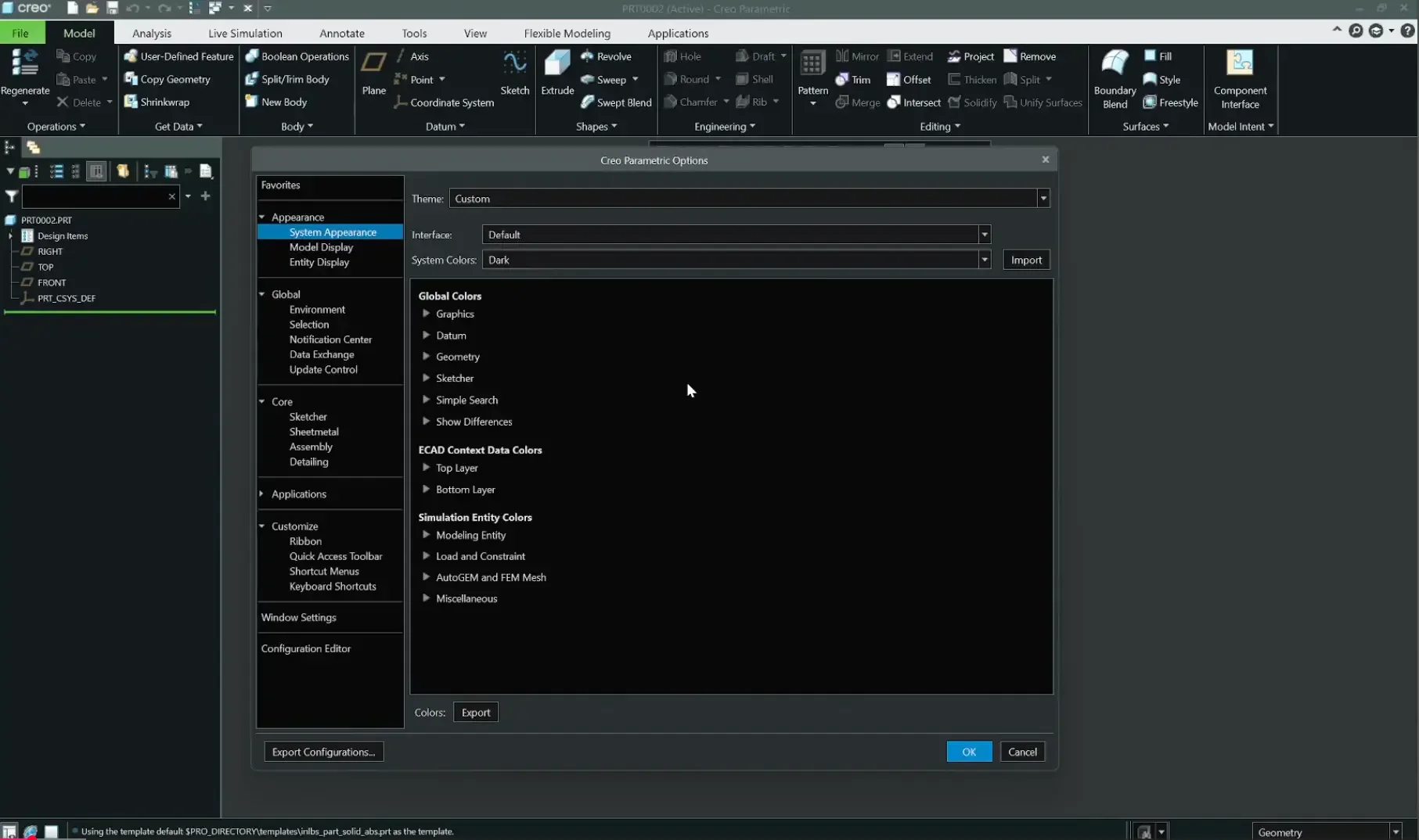
Step 1: Activating "Midnight" Theme & Custom System Colors
If you are working on an OLED monitor or simply want to reduce eye strain during long modeling sessions, the default light theme isn't doing you any favors.
Navigate to the System Appearance tab.
Under the master theme dropdown, switch from default to Midnight.
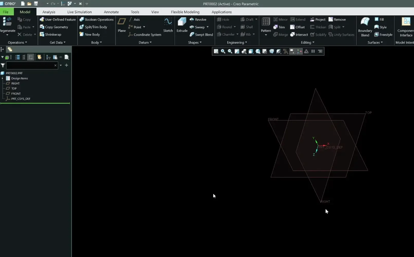
Expand the Graphics subsection to customize your workspace background to solid black (RGBRGBRGBRGB 0, 0, 0).
Click Export to save your custom .scl system color profile to your local documents directory.
Step 2: Model Display Optimization for High-End GPUs
If you have a dedicated workstation graphics card, stop letting Creo throttle your visual fidelity.
Show Datums During Reorientation: Check this box! In vanilla Creo, when you rotate your model, the datum planes instantly disappear. Turning this option on ensures your datum tags stay visible during active model spin.
Maximize Shade Quality: Pull the slider or input value up to 50 (the absolute software maximum). This eliminates jagged facet lines on cylindrical or curved faces, rendering smooth, high-fidelity geometry.
Step 3: High-Quality Surface Edges & 4K Constraint Icons
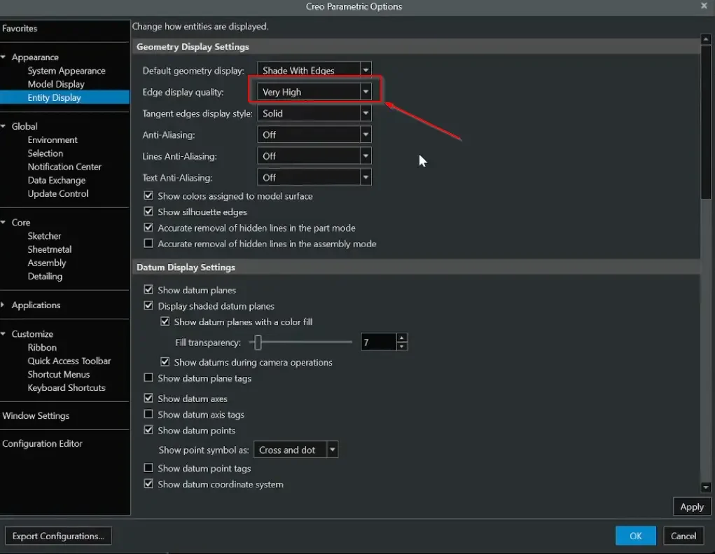
Go to the Entity Display tab to clean up how edges and constraints render on high-resolution screens.
Edge Display Quality: Switch this from Medium to Very High. If you do any advanced surfacing work, having razor-sharp edges is critical for precise geometric selections.
Datum Tags On: Enable plane tags, axis tags, and point tags. This explicitly labels TOP, FRONT, and RIGHT in the viewport so you don't have to keep digging through the Model Tree.
Scale Up Sketch Constraints: Modern 4K laptop screens scale constraint icons down to microscopic sizes. Locate the Constraint Display slider and pull it all the way to the right to make icons large, clear, and readable.
Step 4: Fixing the Broken Sketcher Defaults
The Sketcher environment is where most new users lose their minds. Let's fix the three worst default behaviors.
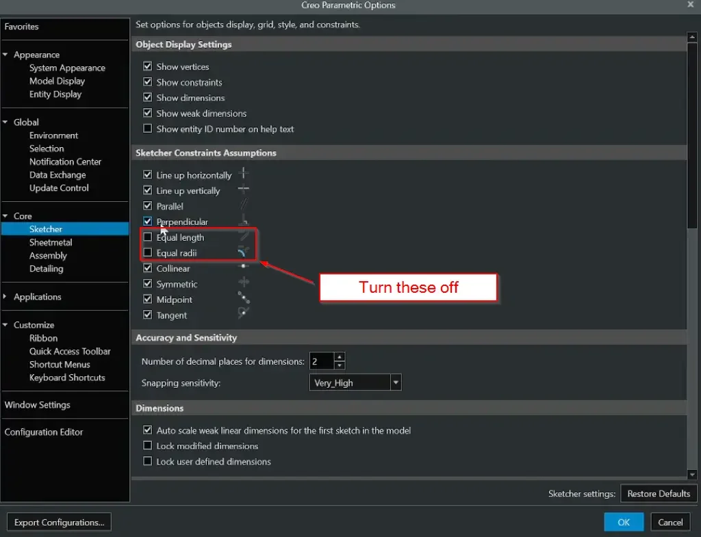
1. Disable Automatic Equal Constraints
Uncheck the options for Equal Length and Equal Radii. Creo's automatic constraint engine is overly aggressive; it will constantly attempt to lock random lines to equal dimensions while you sketch, breaking your design intent.
2. Lock Down Your Strong Dimensions
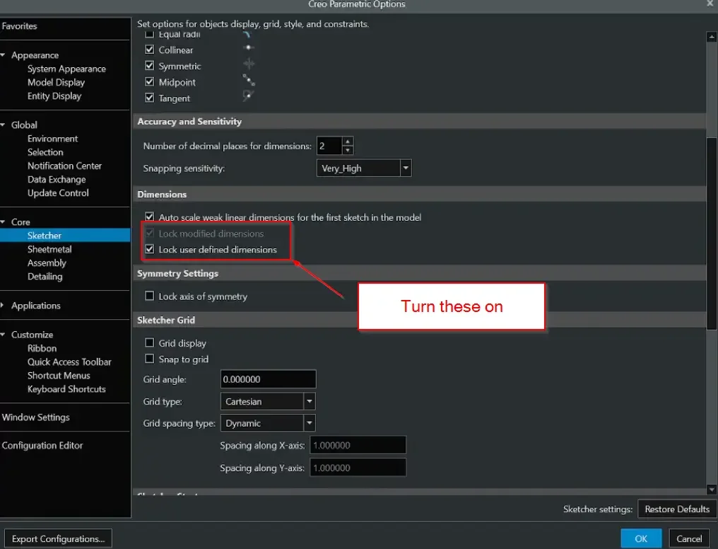
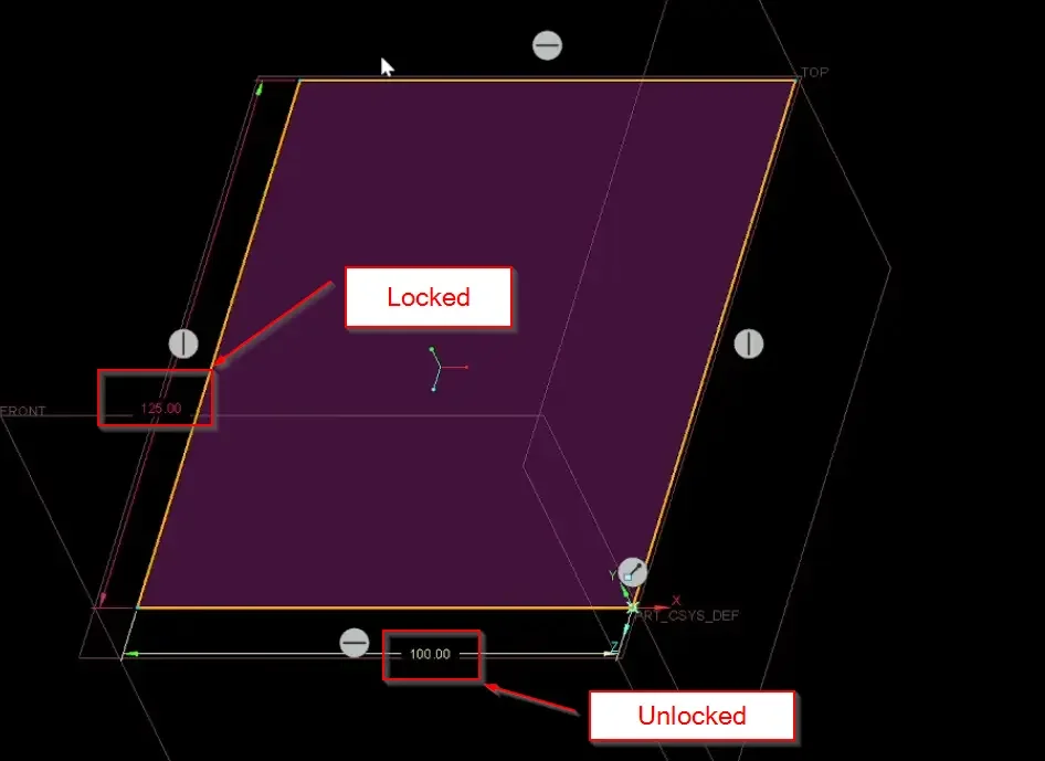
By default, even if you input a strong dimension (e.g., a rectangle side of 100mm), you can still click and drag that line with your mouse, completely altering the geometry. To stop this chaotic behavior, check these two boxes:
Lock modified dimensions
Lock user-defined dimensions
Once activated, user-defined dimensions turn a protective purple hue and freeze firmly in place.
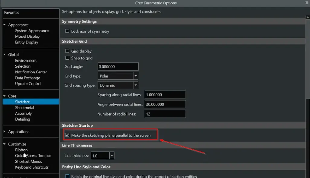
3. Auto-Orient to the Sketching Plane (The Biggest Lifesaver)
Ever notice how clicking a plane and hitting "Sketch" leaves your model sitting at a weird 3D isometric angle? It drives everyone nuts.
Turn on Make the sketching plane parallel to the screen.
Now, the moment you enter a sketch, the camera dynamically auto-flips to a perfect, flat 2D view orientation.
Step 5: Exporting & Saving Your Master config.pro
Once your settings are dialed in, you must export them, or they will completely wipe out the next time you close the software.
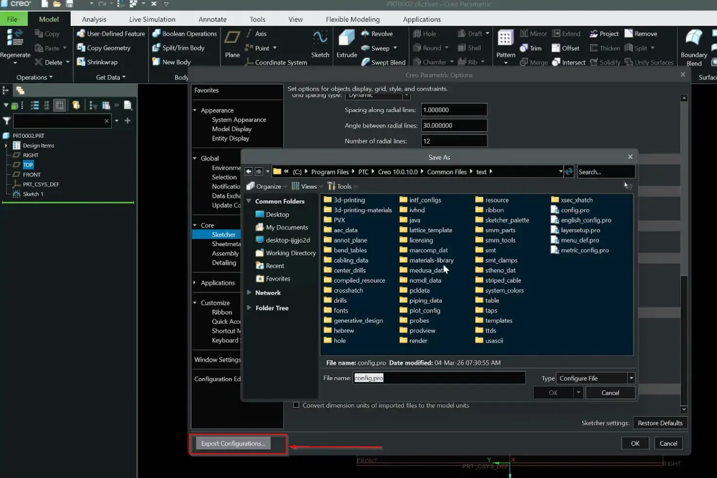
At the bottom of the Options window, click Export Configurations.
Save the resulting config.pro file directly to your desktop or your specific startup directory.
Move the file into your local Creo loadpoint directory using Windows File Explorer (Note: this step may require local administrator write privileges).
Next Steps: Accelerate Your Modeling Velocity & Validation Setup
Optimizing your default system parameters provides a clean, distraction-free environment for serious design work. Keep maximizing your workflow speed and measurement efficiency with these essential Creo guides:
Streamline Your Daily Design Environment: Put your fresh configuration changes to work and learn how to construct bulletproof parametric foundations with our Essential Creo Parametric Sketcher Tips and Tricks.
Calibrate Your Analysis Display Tolerances: Ensure your measurement readouts match your custom config unit systems precisely by exploring our guide on How to Use the Measure Tool in Creo Parametric.
Scale These Workflows Across Your Engineering Team
Standard software tutorials only go so far when facing unique, real-world production bottlenecks. If your design team is struggling with workflow inefficiencies, modeling errors, or assembly instability, we can help.
At JIVE Engineering, we provide specialized, bespoke Corporate Engineering & CAD Training customized entirely around your company’s native production files and internal design standards. We move your team past basic button-clicking and equip them to build robust, failure-proof modeling workflows that save hours of engineering time.
Explore Our Custom Training Programs or Contact Our Team today to discuss your team's specific training needs.