
Advanced Creo Cabling: How to Model Twisted Wires Natively Using trajpar
Whenever the word trajpar gets introduced in advanced CAD classes, engineers often look at the instructor like they are speaking a foreign, encrypted code language.
Don't let the name intimidate you. trajpar stands for Trajectory Parameter, and it is one of the most mathematically powerful arguments you can leverage inside PTC Creo Parametric.
Operating strictly inside the Variable Section Sweep (VSS) environment, trajpar is a built-in system variable that evaluates a local sweep's path as a value ranging from exactly $0.0$ at the starting point to $1.0$ at the absolute end of the trajectory curve. By locking this evaluation into custom sketch relations, you can effortlessly model realistic twisted pair wiring harnesses, braided sleeves, or helical springs without bogging down your system with heavy, unmanageable datum curves.
In this step-by-step tutorial, we look under the hood of a real-world wiring use case: routing a perfectly twisted multi-core wire bundle into an electrical connector backshell.
Watch the Video!
The Core Strategy: The "Dummy Body" Extraction Technique
If you attempt to sweep three independent, spiraling curves simultaneously through standard methods, Creo’s constraint engine will quickly throw calculation errors.
To bypass this limitation, we use an advanced CAD management strategy. We will first sweep a single, flat, multi-sided "dummy body" that twists via trajpar. We then use the sharp outer vertex edges of that temporary twisted block as smooth, guide tracks to host our individual wire paths, deleting the template block at the end of the feature history tree.
Step 1: Layout the Master Guide Path
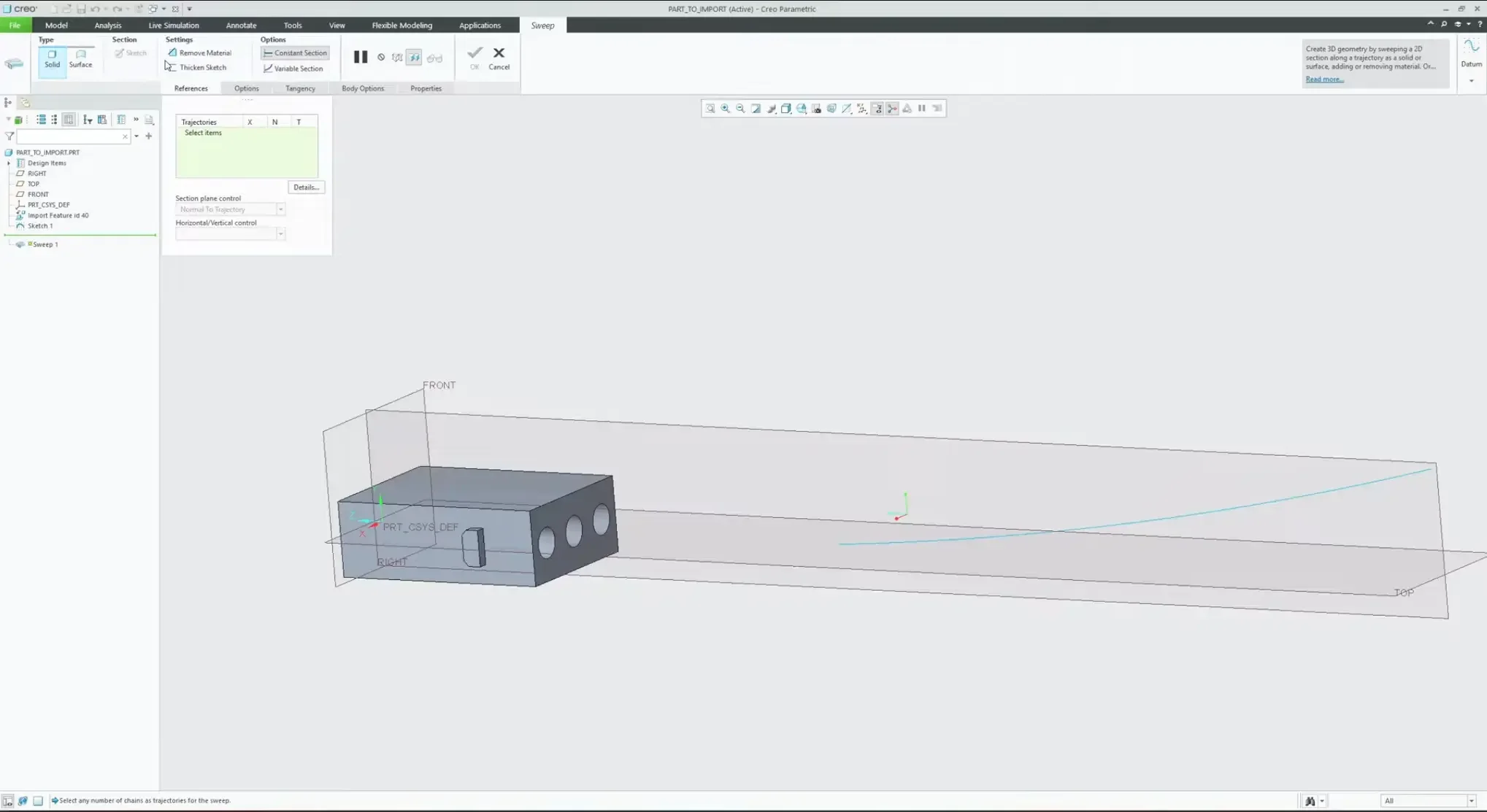
Before writing equations, you need an anchor trajectory line.
Create a 2D sketch or datum curve representing the path your wire bundle takes out of the connector shell.
Select the curve and launch the Sweep command. Ensure your start point arrow is oriented cleanly on the connector side of the path.
Step 2: Sketch the Orientation Vector
Click the Sketch icon to enter the cross-section environment.
Open the Sketcher Palette, navigate to the polygons tab, and drag a 3-Sided Triangle directly onto your cross-section origin point.
Scale the triangle geometry to match your core diameter parameters (e.g., 0.30").
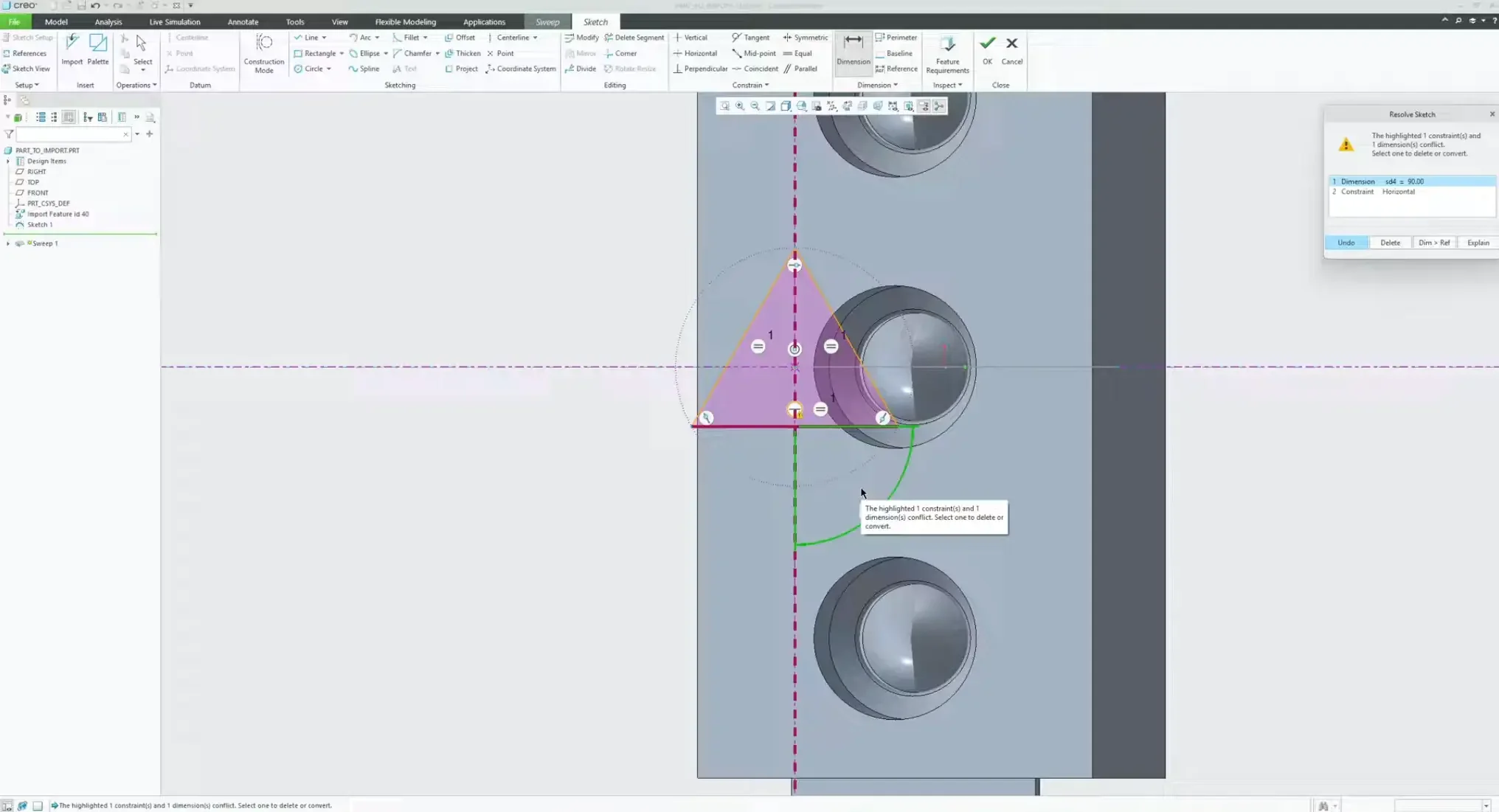
The Freedom Degree Tweak: By default, the palette places a strict horizontal constraint on the baseline curve of the triangle. Highlight and delete that horizontal constraint.
Add a clean angular dimension string measuring from your horizontal datum plane up to the vertical vertex point. Leave it set to its natural 90 degree baseline.
Step 3: Writing the trajpar Relation Equation
With your angular parameter defined, we need to bind its behavior to the sweep's location.
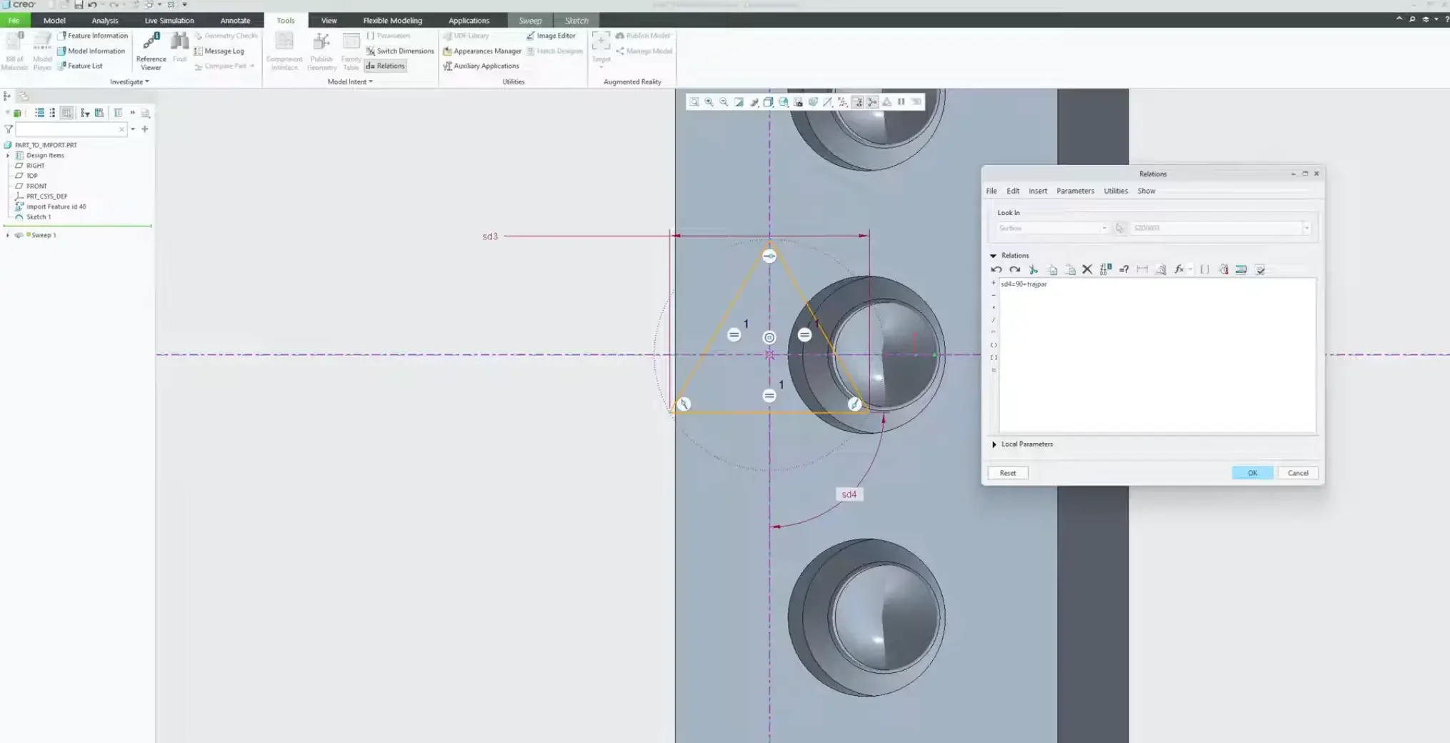
Navigate to the Tools tab at the top of the ribbon and select Relations.
Note the system parameter ID assigned to your angular dimension (for example, SD4).
Inside the relation editor window, write the following expression precisely:
SD4 = 90 + trajpar * 360
Breaking Down the Math Matrix:
At the start of the path trajpar = 0, the formula calculates as:
90 + (0*360) = 90
At the midpoint of the path ($\text{trajpar} = 0.5$), it shifts to:
90 + (0.5*360) = 270
At the terminal exit of the path ($\text{trajpar} = 1$), it evaluates as:
90 + (1*360) = 450
This tells Creo to spin the geometry exactly one full 360 rotation along the trajectory line. If your design requires a tighter pitch with multiple revolutions, simply multiply the end value (e.g., trajpar 360 2 for two full twists). Verify the syntax and click OK.
Step 4: Generating and Isolating the Multi-Body Matrix
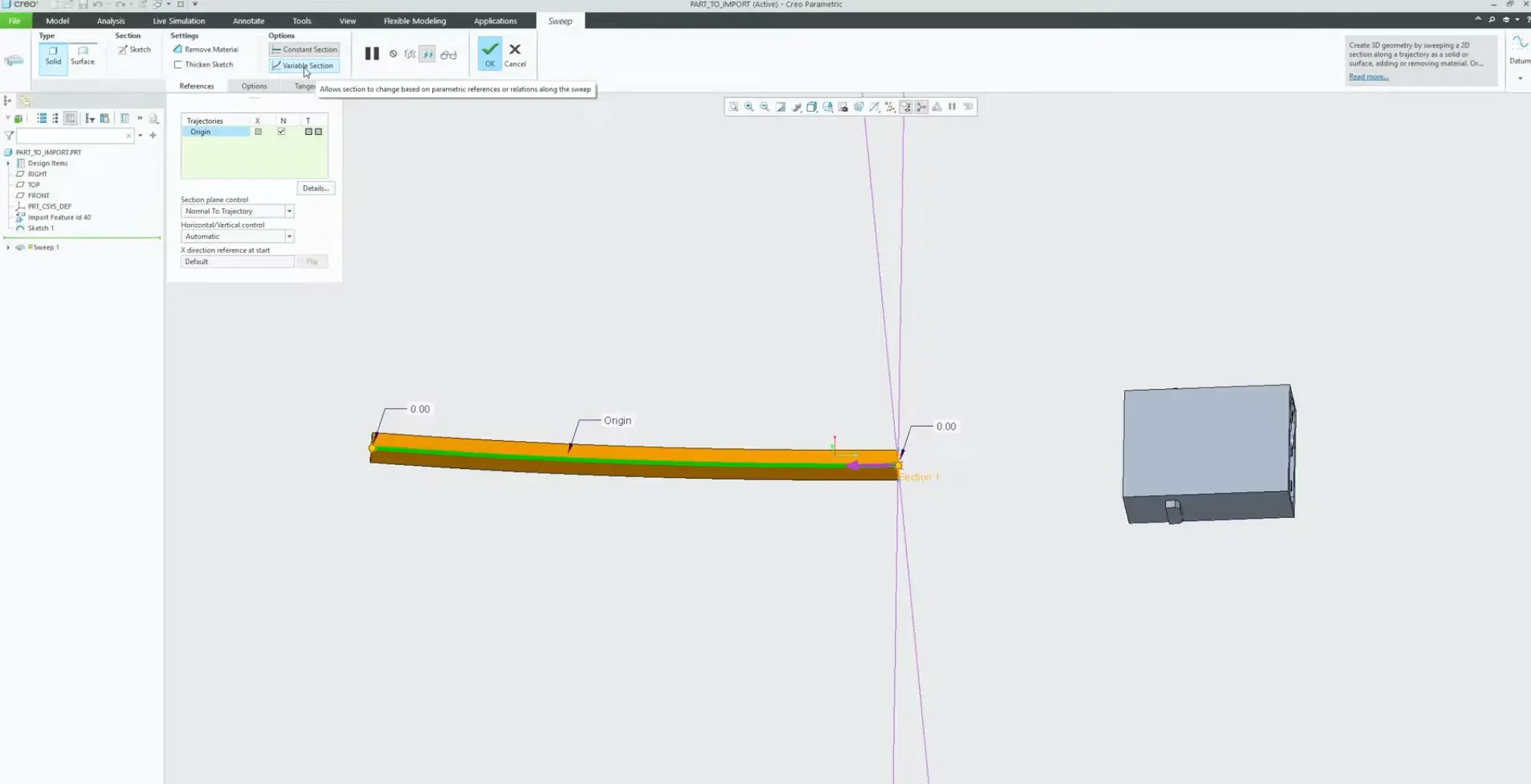
When you exit the sketcher, the profile might look identical in its initial 2D view.
Ensure Variable Section is active on your dashboard menu to watch the solid geometry dynamically helix.
Go to the Body Options tab on the command dashboard and select Create New Body. This isolates our twisting template form into a separate system item so it doesn't accidentally merge with the connector shell. Click OK.
Step 5: Clocking Wire Centerlines into Connector Pins
Now that we have our twisting core template on screen, we need to transition those sweeping corner tracks out to individual pin locations.
Create a Datum Point centered at the mouth of each of your three connector pin entry points.
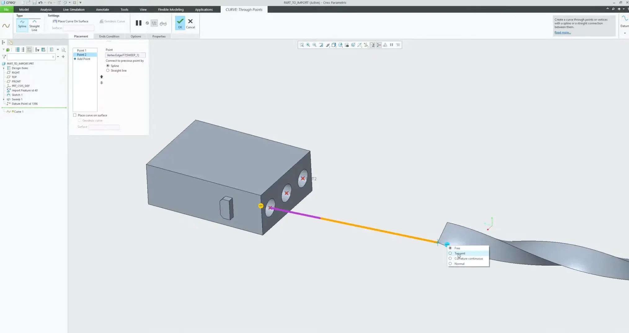
Launch the Curve through Points tool.
Select a terminal vertex point from the end of your twisted dummy block and connect it directly to its corresponding pin entrance point.
Enforcing Continuity: Right-click the curve endpoint selection constraint and set it to Tangent matching the edge of your twisted block, and Normal matching the flat face of the connector entry. Repeat this step for all three curves.
Step 6: Sweeping the Core Strands and Removing the Template
With your three smooth composite centerlines mapped, you can now run your final production sweeps.
Launch a new Sweep feature.
Avoid User Error: Do not simply hold $Ctrl$ and click individual segment paths. This forces Creo to process them as competing trajectories. Instead, open the Details dialogue menu on your reference selection and combine the curves into one unified Composite Chain.
Sketch a circle corresponding to your actual copper gauge wire thickness, select Create New Body in your body parameters, and finish the feature.
Copy and paste the sweep sequence to cleanly populate the remaining two guide curves.
The Final Cleanup: In your Model Tree or Body folder, click on the original twisted dummy block body we generated in Step 4, right-click, and select Remove Body.
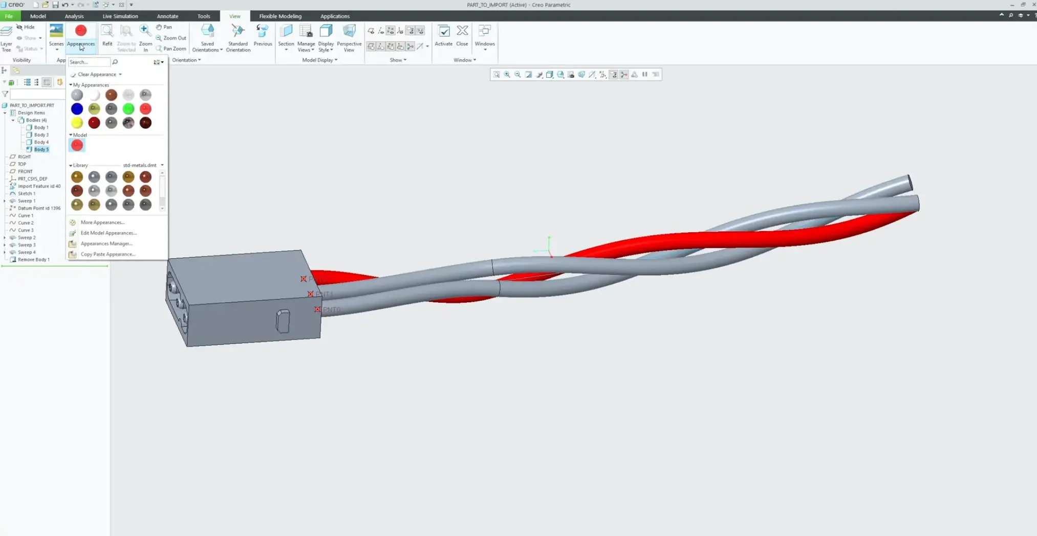
Because we isolated the block onto its own multi-body node, it vanishes from the viewport instantly without collapsing or breaking any of the child curve dependencies tied to its geometry. Add custom appearance colors to your core wires (Red, Green, Blue), and your advanced harness layout is complete.