
Creo Parametric Hack: How to Pattern Features Across Complex Contoured Surfaces
If you have spent any significant time modeling complex body panels, aerospace skins, or consumer electronic casings inside PTC Creo Parametric, you have likely run into a frustrating wall: patterning features across a non-planar, curved, or contoured surface.
Watch the Video!
If you try to resolve this problem using a traditional direction or axis pattern, your instances will stay locked to a flat coordinate plane, flying straight off into open space as your surface contour dips away. The feature fails because it doesn't adapt to the shifting surface normals.
To solve this, many engineers click on the "Curve Pattern" option, only to watch Creo throw an error. Why? Because Curve Patterning in Creo strictly requires a 2D sketch. If you are dealing with a complex 3D contour or imported neutral geometry (STEP/IGES), a flat sketch won't work.
The ultimate pro-level workaround is to use a Pattern by Dimension driven by a single parameter ratio (0 to 1) mapped along a 3D composite curve. Here is exactly how to set up the geometry framework to build a bulletproof, surface-normal pattern.
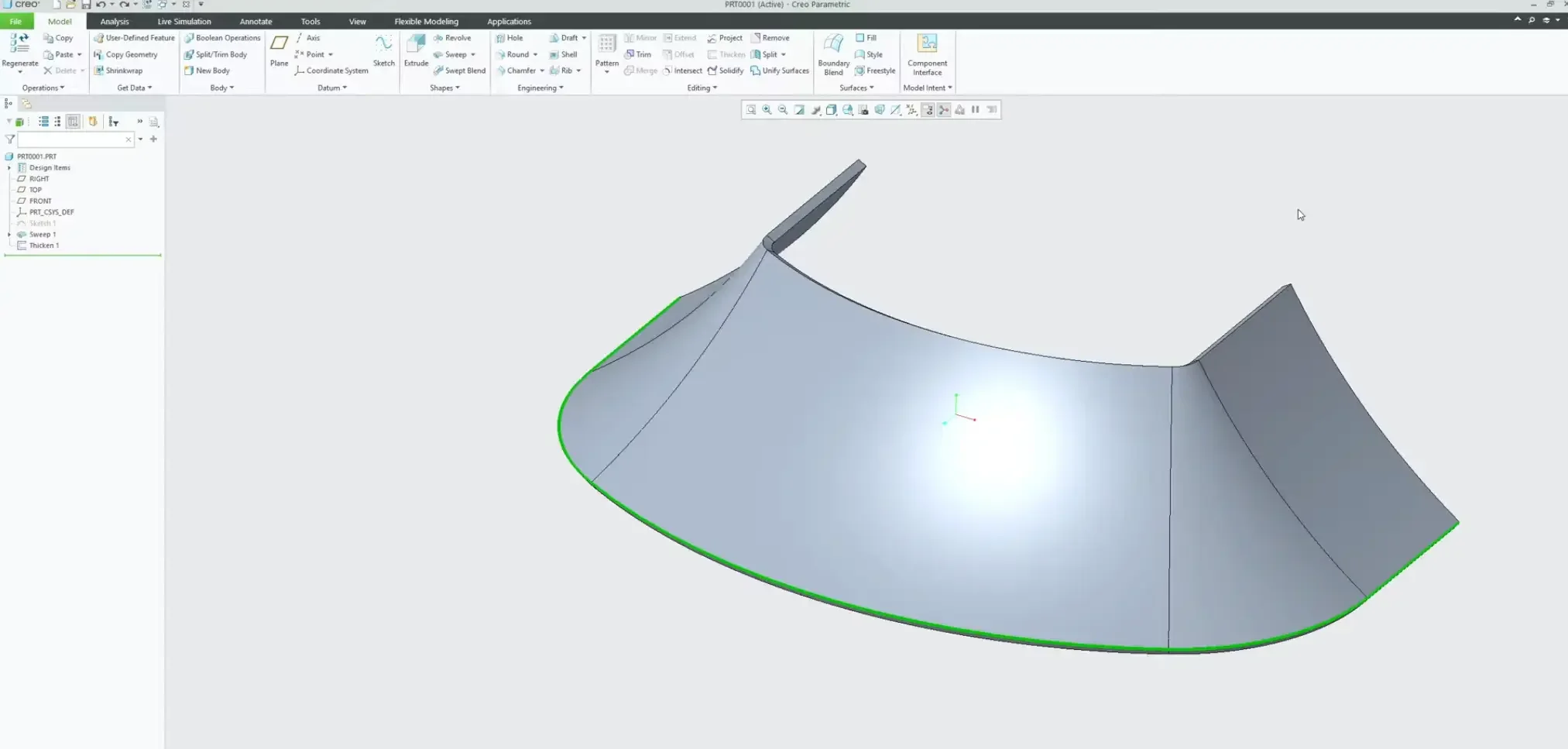
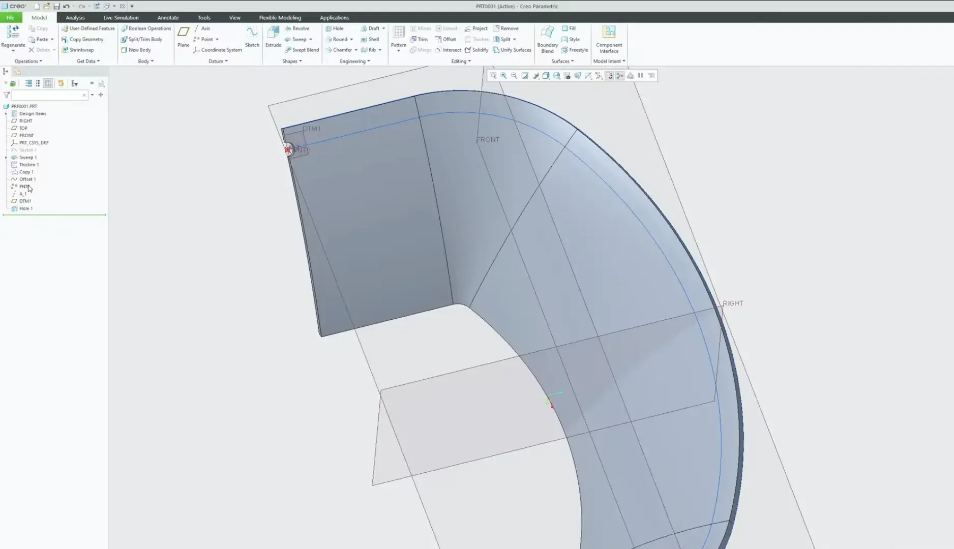
Step 1: Extract and Offset a 3D Composite Curve
If you are working with an imported neutral model or don't want to dig through a dense feature tree to find an original sketch, you can generate a master guide track directly from the model's 3D edges.
Select a starting edge along the lip or contour where your pattern needs to travel.
Navigate to the opposite end of your target boundary, hold the Shift key, and select the closing edge. Creo will instantly select the entire tangent chain block of curves.
Use the standard keyboard shortcuts Ctrl + C and Ctrl + V to copy and paste the geometry. This creates a clean, independent Composite Curve feature in your Model Tree.
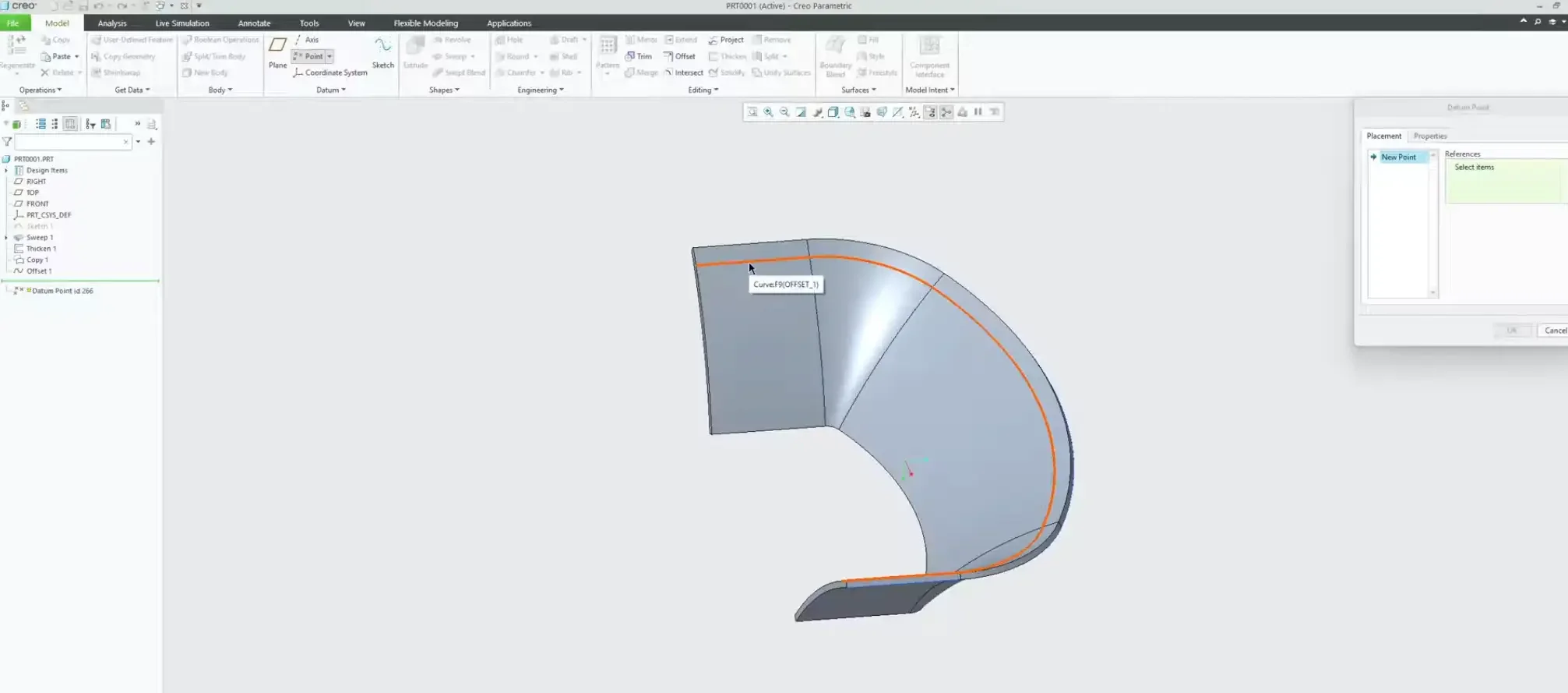
With the new curve highlighted, use the Offset tool to position the path precisely where your features should sit relative to the face boundaries (e.g., 10mm offset).
Step 2: Parameterizing the 3D Guide Chain
Now we need to anchor a datum point that can fluidly slide from the beginning of our 3D track to the absolute end.
Click the Datum Point tool.
Hover over your offset curve, and click the Right Mouse Button (RMB) once. This query-select shift allows you to select the entire composite chain rather than an isolated segment.
Look at your point properties. By selecting the full chain, Creo transitions the location reference into a Ratio parameter where 0.0 represents the exact starting tip of the track and 1.0 represents the terminal end point.
Important Best Practice: Enter 0 as your starting ratio value to park the datum point precisely at the absolute beginning of the track. Do not place it down the line yet—we will let the pattern engine manage the distance translation downstream. Click OK.
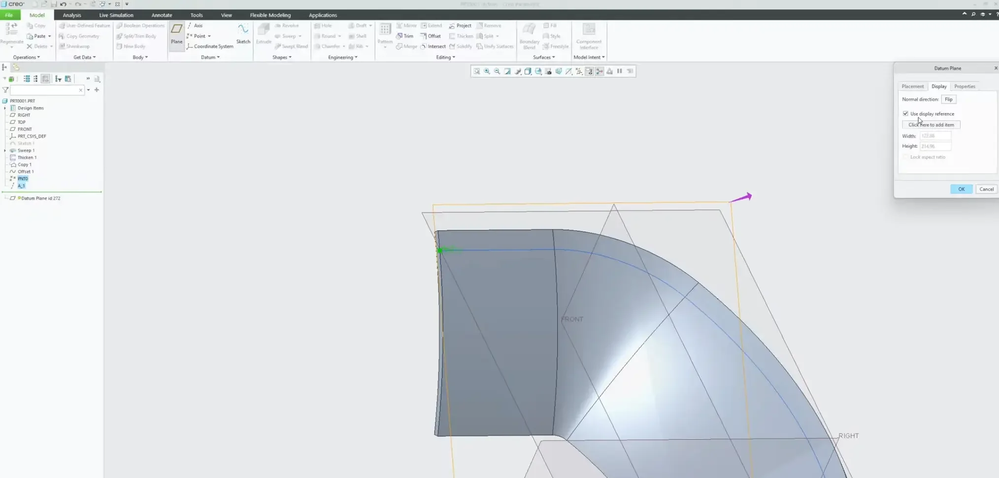
Step 3: Establishing the Surface-Normal Datum Framework
To ensure your patterned features dynamically rotate and stay perpendicular to the shifting face profile, you must build a self-correcting datum framework anchored directly to your sliding point.
Create a Datum Axis: Select your sliding datum point, hold the Ctrl key, select the contoured surface face, and set the constraint rule to Normal. This creates an axis that dynamically recalibrates its angular tilt to stay perfectly perpendicular to the face contour at that exact point.
Create a Datum Plane: Select your sliding datum point and hold Ctrl to select the newly created datum axis. Set the relationship to Normal.
Admin Cleanup: Scale down the boundary sizes of your new axis and plane right now within their display properties. If you leave them at their massive default sizes, they will visually clutter your viewport once they multiply across the pattern sequence.
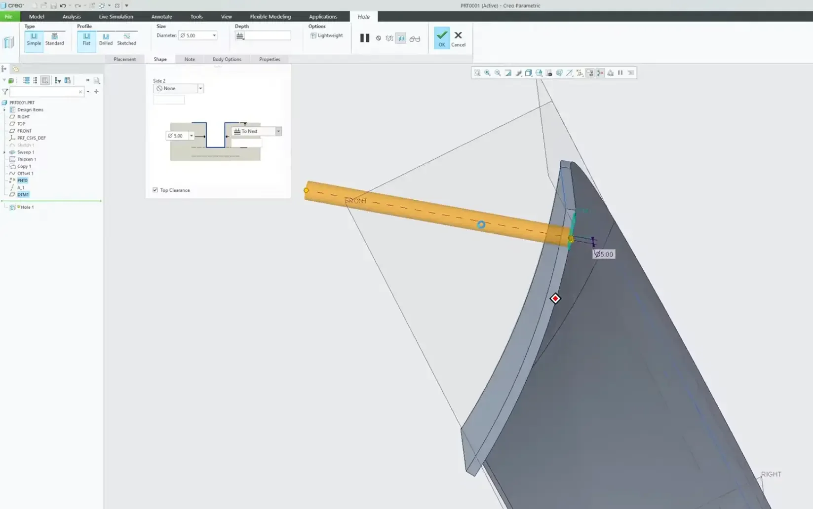
Step 4: Modeling the Base Feature (Set to Next)
With your localized tracking framework completely built, you can now host your design feature—such as a hole or an extrusion.
Launch the Hole command.
Place the hole center directly on your sliding datum point, hold Ctrl, and select your surface-normal datum axis to lock in the punch direction.
The Termination Trap: Never leave the hole depth termination set to a blind numeric value. If your model thickness tapers down the line, a blind hole could punch completely through or stop short.
Open the Shape tab dropdown menu and explicitly select To Next. This ensures that every single pattern instance intelligently calculates the localized wall thickness and terminates perfectly flush at the interior wall face.
Step 5: Grouping the Geometry Matrix
Before you can execute the pattern command, you must explicitly group your entire structural stack. If you try to pattern the hole feature by itself, it will break because the underlying tracking datums won't follow it.
In the Model Tree, hold Ctrl and select the Datum Point, Datum Axis, Datum Plane, and the Hole feature.
Right-click the highlighted block and select Group.
Name the group something clear, such as hole_geometry_grp.
Step 6: Configuring the Pattern by Dimension Matrix
This is where the magic happens. We are going to tell Creo to propagate our grouped geometry matrix by incrementally stepping our original point ratio value from 0.0 toward 1.0.
Highlight your geometry group and click the Pattern tool.
Open the pattern type dropdown menu on the dashboard and select Dimension.
Click on the grouped datum point feature to reveal its background dimensions. Select the original 0 ratio dimension parameter as your primary driving variable.
In the dimensions increment matrix box, define your pitch spacing step:
Example Layout: If you want 10 evenly spaced holes stretching across the entire path length, input an increment value of 0.1 (since the total path is evaluated from 0 to 1).
In the instance count box on the dashboard, input your total quantity. Remember that your original parent feature counts as item number one, so to get 10 downstream instances, enter a total count of 11.
Hit the green checkmark OK.
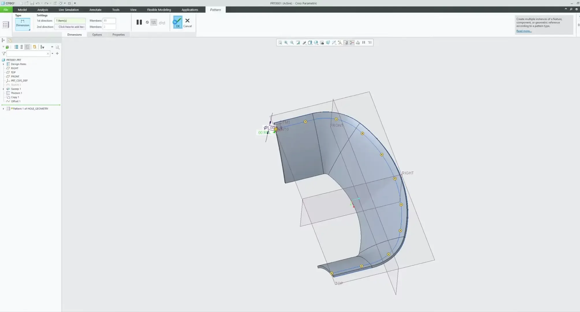
Creo will effortlessly calculate the tracking ratio, rebuild the surface-normal datums at every step, punch the holes with clean "To Next" face terminations, and deliver a flawless, contour-following pattern array.