
How to Apply Text to Any Surface in Creo Parametric
Watch the Video!
Need a video to help you through this process? Feel free to check out the video down below!
Have you ever tried to emboss or engrave a logo, serial number, or string of text onto a complex curved or cylindrical surface inside PTC Creo Parametric?
If you are using legacy workflows, you probably tried to sketch the text, project or wrap it, and then run a standard solid extrude. But on complex contours or non-planar faces, Creo's solid extrusion tool quickly throws geometric generation errors. This happens because a standard extrusion travels along a single straight vector, causing the letters to warp, distort, or lose their thickness as the underlying surface dips away.
The ultimate power-user workaround is to completely skip the extrusion tool. By leveraging the modern Divide Surface tool (introduced in Creo 10) alongside Flexible Modeling Offset, you can effortlessly create clean text that stays perfectly normal (perpendicular) to the surface contour at every single coordinate point.
Here is your step-by-step framework to wrap text cleanly around literally any shape.
Step 1: Establish a Tangent Text Placement Plane
To start, we need a flat space to anchor our initial text sketch right in front of our curved model face.
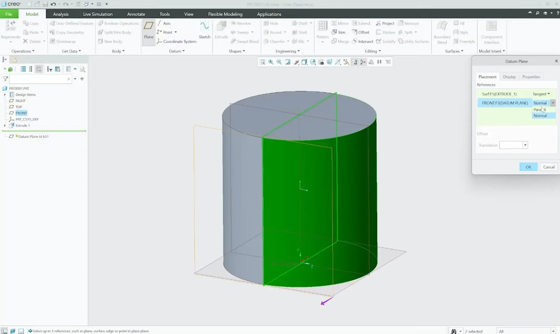
Navigate to the Model tab and launch the Datum Plane tool.
Select the curved surface of your part as your primary reference and set the constraint to Tangent.
Hold the Ctrl key, select a flat orthogonal base plane (such as the FRONT plane), and set the relationship to Parallel. This aligns your new plane perfectly square to the face of the cylinder.
Step 2: Sketch the Text and Curve References
With your new plane active, we will build a construction line to precisely locate and center our text.
Open the Sketcher on your new datum plane.
Draw a simple horizontal line to act as a baseline guide track. Dimension it cleanly to size (e.g., 100mm).
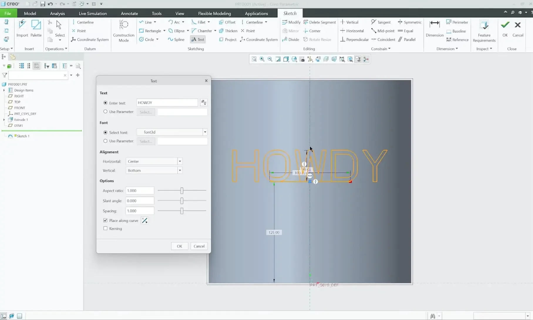
Select the Text tool. Click the left starting point of your line and drag upward to define the text height boundary.
Input your text string (e.g., "Howdy").
In the properties matrix, check the box for Place along a curve and select your horizontal guide line.
Adjust the alignment dropdown options: set horizontal to Center and vertical to Middle to lock the text squarely onto your line.
Critical Best Practice: Before exiting the sketcher, highlight your original guide line and select Convert to Construction. If you leave it as solid geometry, it will interfere with the downstream surface splitting operations. Click OK.
Step 3: Projecting the Text Onto the Curved Profile
Now we need to translate our flat 2D text into a 3D path wrapping around our curved face.
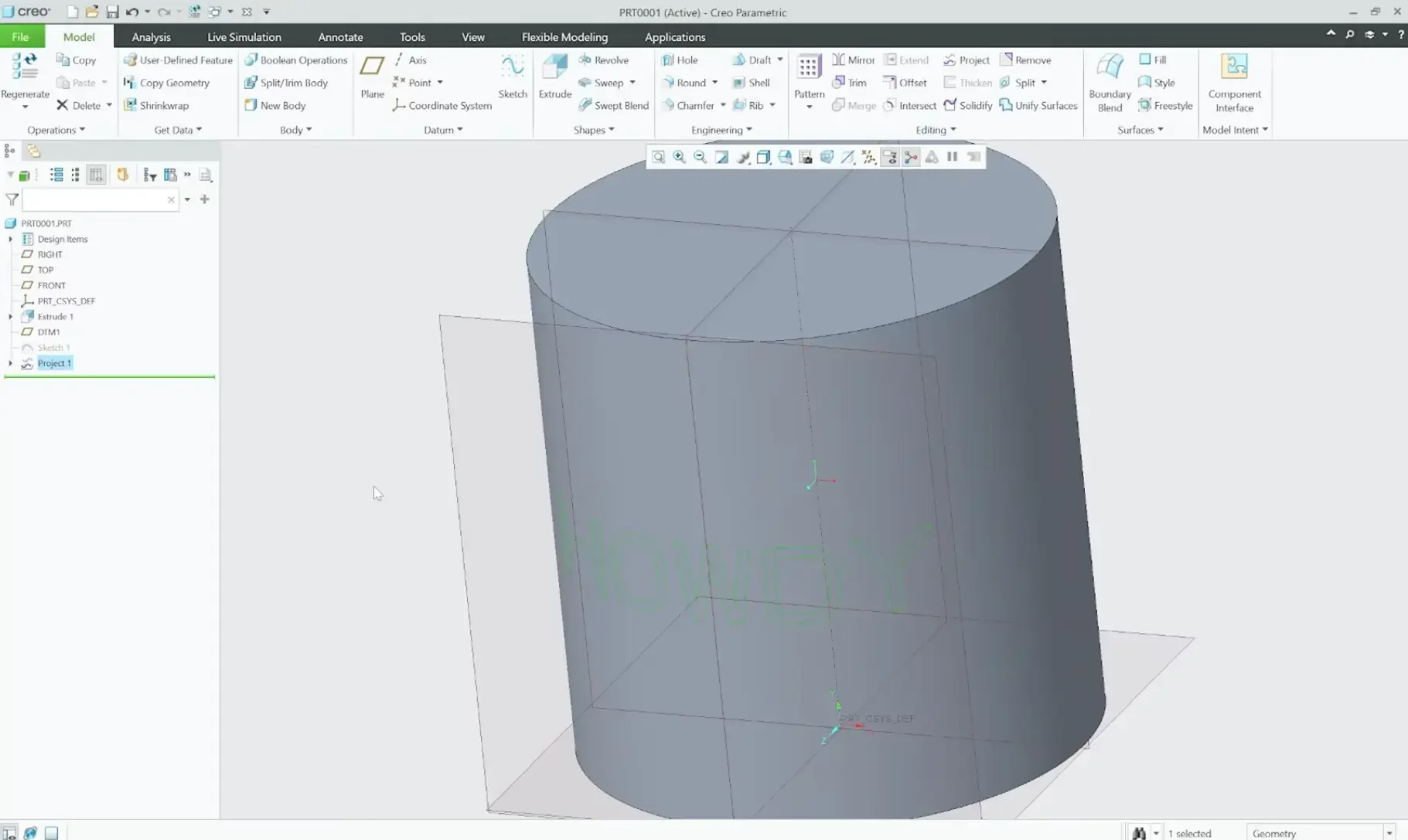
Highlight your text sketch feature in the Model Tree.
On the main ribbon, execute the Project command.
Select the outer cylindrical surface as your target face and click OK. Your text path will instantly project back, wrapping flawlessly around the contour.
Step 4: Splitting the Face Matrix via Divide Surface
Historically, in legacy versions of Creo, you were not allowed to split an integrated solid face using an open curve or projection path. However, starting in modern versions like Creo 10, the software introduces advanced surface subdivision mechanics.
Go to the editing section of your ribbon and open the Split dropdown menu.
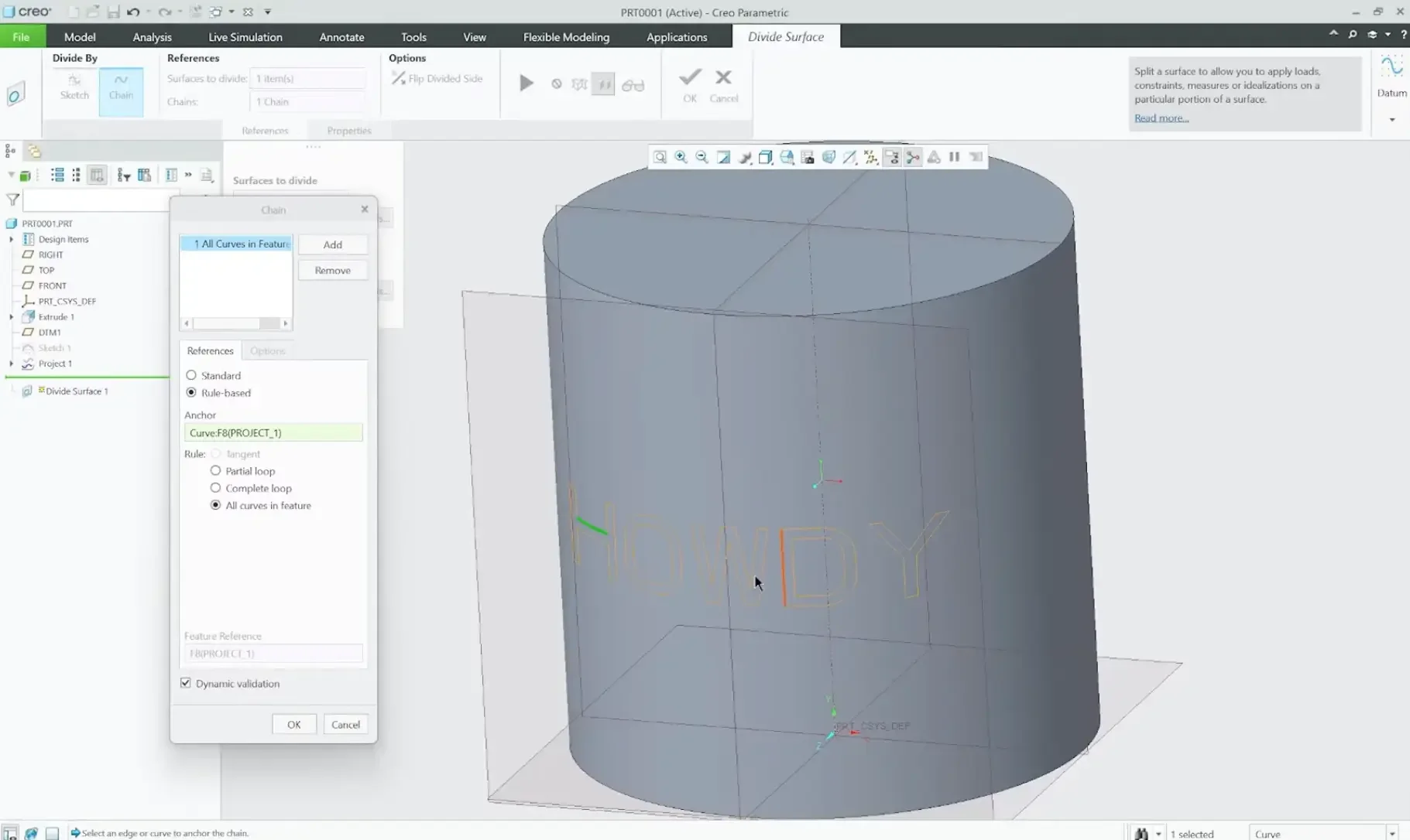
Select Divide Surface.
Set the target reference to your outer cylindrical face.
Switch the subdivision input option from Divide by Sketch to Divide by Chain.
The Workflow Shortcut: Rather than manually clicking dozens of tiny letter curves one by one, click the Details button in your selection panel to open the rule-based selection tool.
Change the rule criteria to All curves in feature and select just a single segment of your projected text. Creo will instantaneously highlight every line in your text block automatically. Click OK.
When you hit the green checkmark, Creo divides the master profile. While it visually looks like individual letter faces, Creo initially groups this boundary as two primary topological regions: the main body face, and the combined "text text region" face loop.
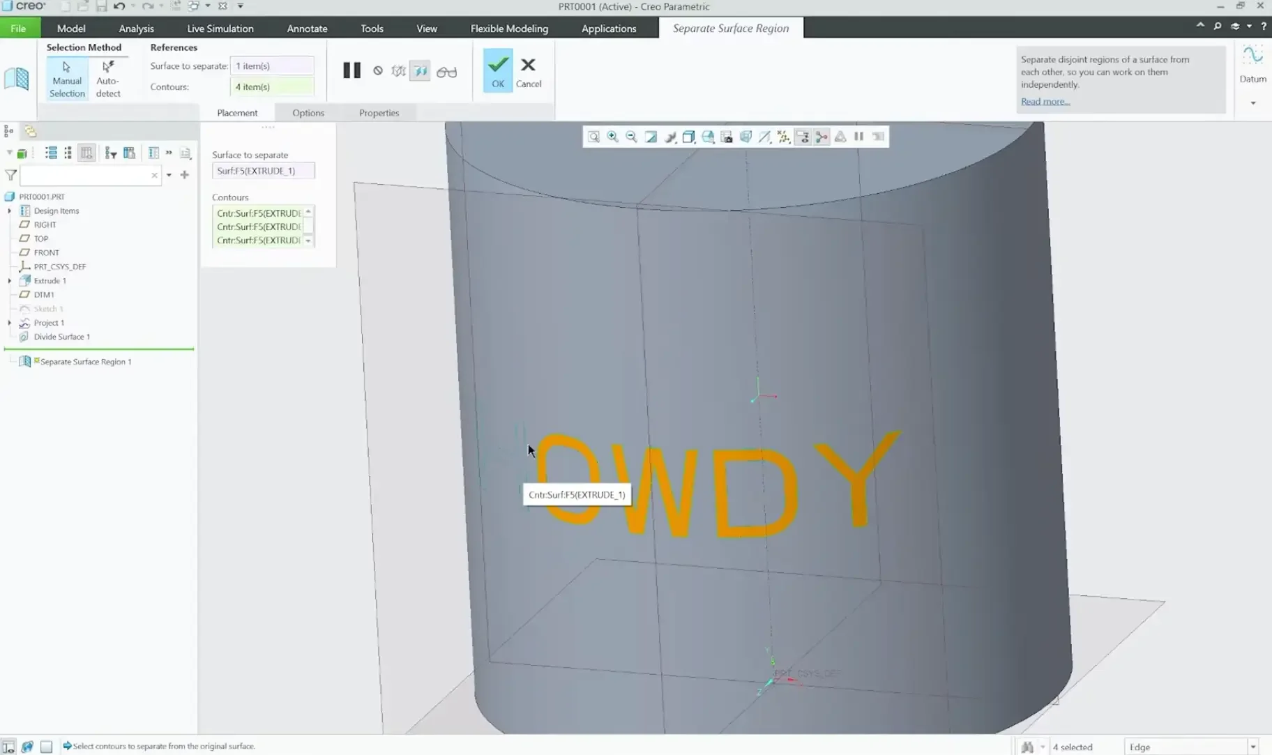
Step 5: Separating Surface Regions for Complex Topology
If you are dealing with a standard cylinder, the unified text face loop works perfectly. But if you are working with a highly complex multi-contoured part, a single consolidated face region can sometimes throw downstream calculation errors.
To give yourself absolute editing control, you can split the text loop down into independent individual letter faces:
Open the Split dropdown menu again and select Separate Surface Region.
Select your combined text face region.
Hold the Ctrl key and select each individual letter contour loop sequentially (e.g., the H, the o, the w, etc.) to break them apart. Click OK. Every letter is now its own isolated, cleanly modifiable face entity.
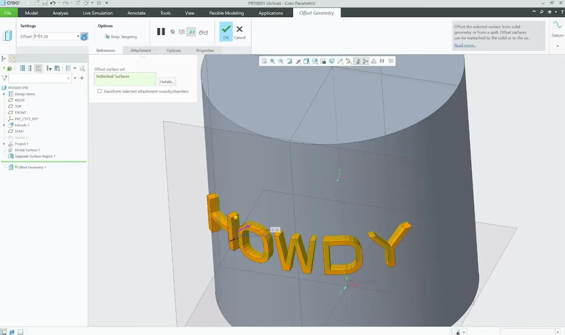
Step 6: Leveraging Flexible Modeling for the Perpendicular Offset
With the text faces cleanly subdivided into the model geometry, we can use the Flexible Modeling Extension (FMX) to pull or push the letters. FMX calculates offsets normal to the local surface face, entirely bypassing flat vector extrusion restrictions.
Switch over to the Flexible Modeling tab at the top of your ribbon layout.
Highlight your text faces, and execute the Offset tool.
To emboss the text (raise it out of the surface), input a positive numeric value.
To engrave or deboss the text (recess it into the part), toggle the flip vector arrow on the dashboard to switch to material removal mode.
Hit OK to process. Because the calculation runs normal to the local surface boundary, your text maintains a perfectly uniform depth and crisp edge clarity, no matter how aggressively your underlying geometry curves.
Pro Tips for Perfect Results
Keep it Simple: Small, intricate fonts can be difficult to manufacture. Stick to clean, sans-serif fonts if the part is being 3D printed or CNC machined.
Draft Angles: If you are designing for injection molding, don't forget to add a small draft angle to the sides of your embossed text so the part can be removed from the mold!
Conclusion
Adding text in Creo Parametric doesn't have to be a headache. This technique will work with almost any type of surface, guaranteed.
Next Steps: Master Complex Surfaces & Sketch Integrity
Projecting clean text profiles onto curvature is just one aspect of advanced surface detailing. Deepen your geometric control and maintain stable parametric relationships with these essential Creo guides:
Array Detailing Along Curvature: Once you master placing geometric details or cosmetic features on curved faces, learn how to replicate them dynamically using our tutorial on Patterning on Contoured Surface in Creo Parametric.
Build Bulletproof Sketch Geometry: Text wraps can easily break if the underlying fonts or references are unstable. Secure your sketch geometry and parent-child relationships using our Essential Creo Parametric Sketcher Tips and Tricks.
Scale These Workflows Across Your Engineering Team
Standard software tutorials only go so far when facing unique, real-world production bottlenecks. If your design team is struggling with workflow inefficiencies, modeling errors, or assembly instability, we can help.
At JIVE Engineering, we provide specialized, bespoke Corporate Engineering & CAD Training customized entirely around your company’s native production files and internal design standards. We move your team past basic button-clicking and equip them to build robust, failure-proof modeling workflows that save hours of engineering time.
Explore Our Custom Training Programs or Contact Our Team today to discuss your team's specific training needs.