Step-by-Step Guide: Creating and Saving Exploded Views in PTC Creo Parametric
Exploded assembly views are vital for downstream documentation, production floors, and design reviews. They allow technical illustrators and operators to visualize the layered stack-up of components without guessing how internal fasteners or gaskets interface.
In PTC Creo Parametric, an exploded view is completely non-destructive. It does not delete or break your core assembly placement constraints. Instead, it lives as a specialized snapshot state fully managed within the View Manager.
However, Creo's explosion interface contains a famous trap: if you don't explicitly save your position updates inside the View Manager manager matrix before exiting, your entire layout will stubbornly snap back to normal, wiping out your work. Here is how to configure a bulletproof exploded view step by step.
Watch the Video!
Step 1: Initialize the View Manager Configuration
To create a clean explosion, you must isolate your layout away from the standard modeling camera configurations.
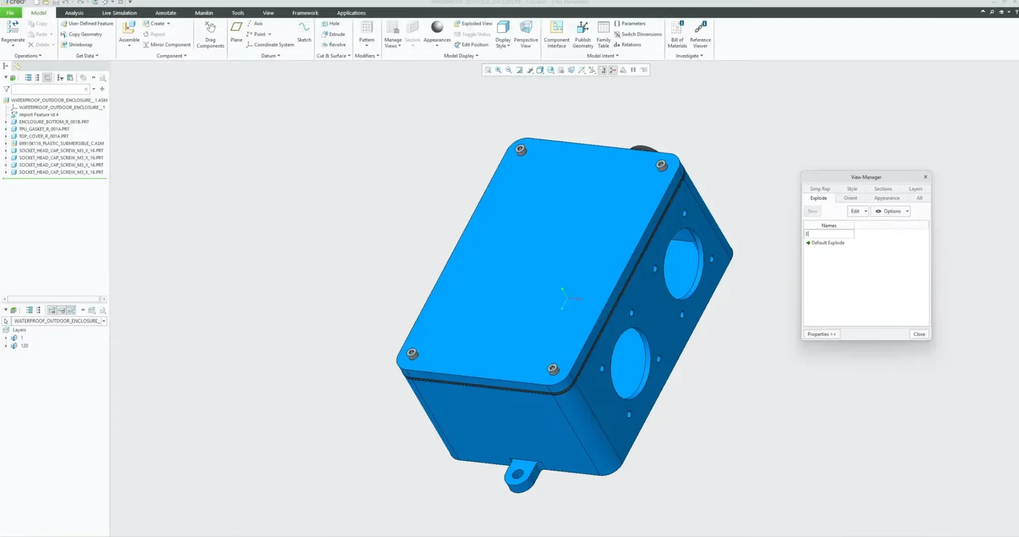
Navigate to the top ribbon tab and open the View Manager dialog window.
Click on the Explode tab.
Select File > New, enter a descriptive configuration name (e.g., explosion_1), and press Enter.
Right-click your new explosion line item and select Edit Position to launch the manipulation dashboard.
Step 2: Set the Motion Increment and Displace Components
Creo relies on manual translation coordinates, giving you absolute control over how clusters move through 3D space.
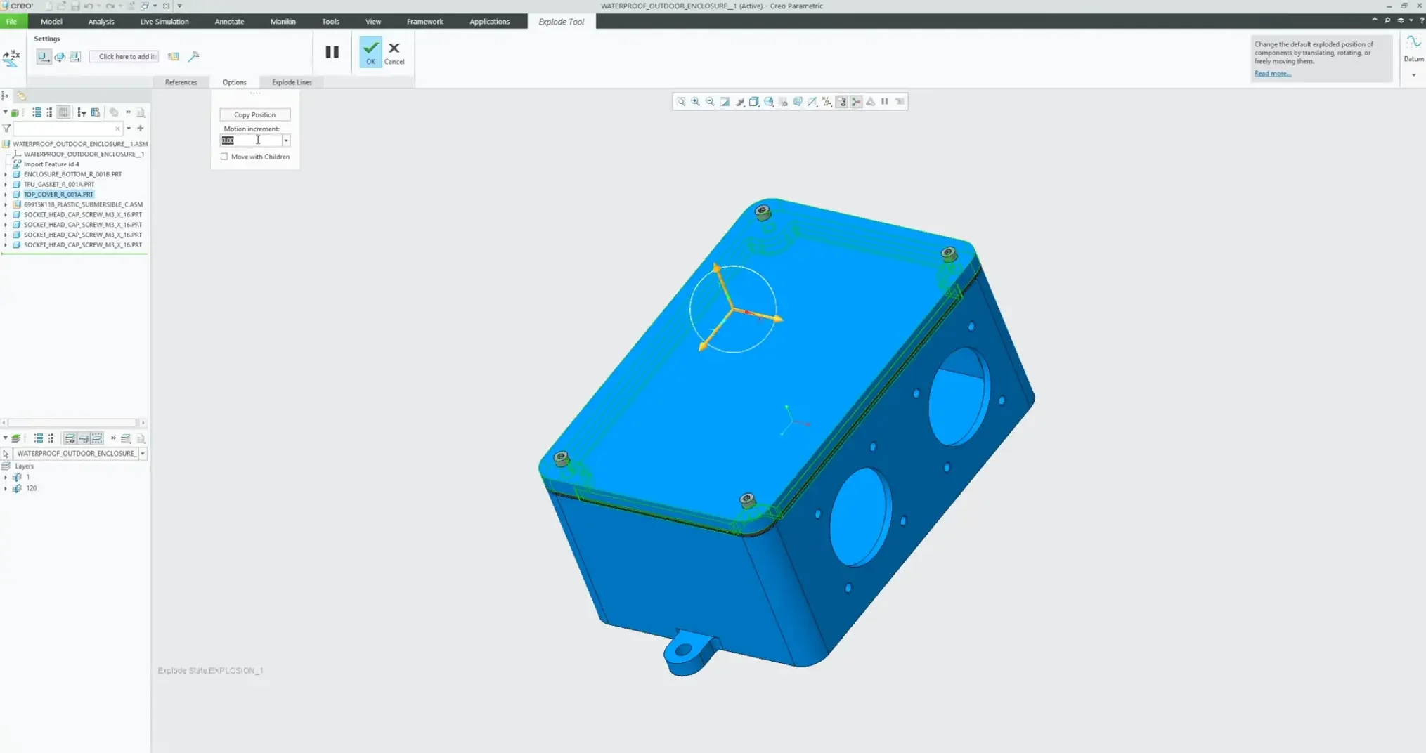
Click on the target component you want to move. To select multiple parts simultaneously (like a row of hardware), hold the Control key while clicking.
To shift focus to a separate component stream, simply left-click the new item without holding Control.
Use the directional vectors of the on-screen triad handle to translate the parts out of their sockets.
The Grid Snap Trick: To keep your spacing perfectly uniform, go to the Options panel on the dashboard and look for Motion Increment. If you input a value (such as 0.5 or 2.0), the triad will cleanly snap by that exact numeric interval every time you drag your mouse, saving you from sloppy, uneven gaps.
Step 3: Draw Center-Line Cosmetic Explode Lines
To link floating hardware back to its mating internal thread structure across complex assemblies, we use Cosmetic Explode Lines.
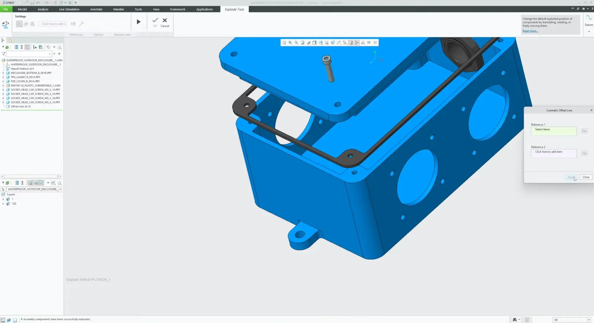
Click on the Explode Lines button on the dashboard.
Select Create.
Rather than trying to pick abstract center points, hover over your hardware and select a cylindrical surface face. Creo will instantly lock onto the center axis.
Select the corresponding cylindrical surface face of the target hole structure on your base part.
Click Apply. Creo will automatically bridge the gap with a clean, dashed tracking line that stays perfectly associative to the features.
Step 4: The Critical Step — Saving Your Exploded State
To permanently bake your layout adjustments into the model's history file:
Finish your layout additions and click OK on the movement dashboard.
Return to the open View Manager dialog panel.
Right-click on your custom explosion_1 configuration node.
Select Save from the context dropdown menu, then click OK to confirm. Your configuration parameters are now safely integrated into the model database.
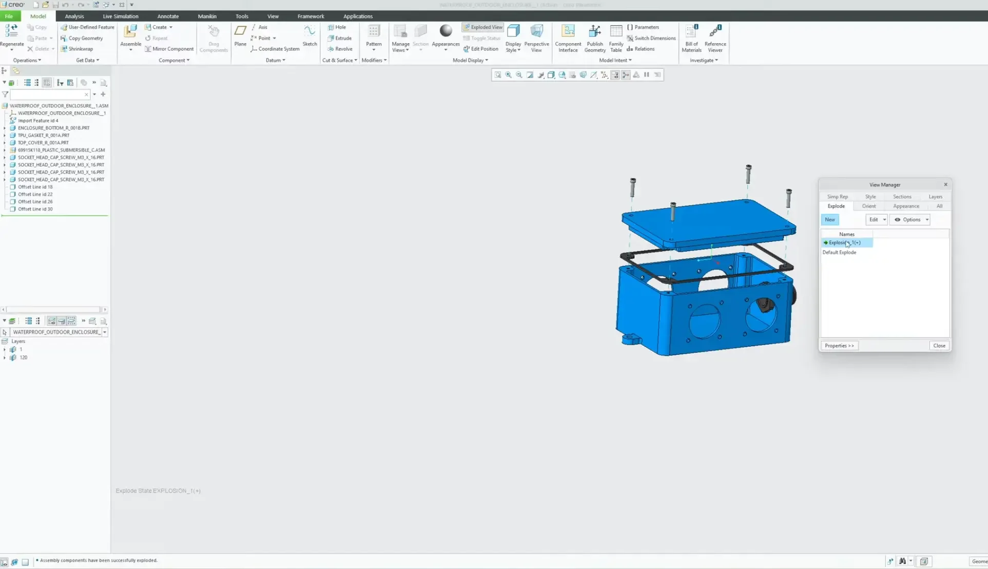
Step 5: Toggling and Utilizing View Configurations
Now that your view state is safely saved, you can cleanly toggle between design modes on the fly:
To snap back to standard modeling space, select the Explode button on the top ribbon menu to deactivate the state. Your assembly instantly telescopes back together to its original constraint matrix.
To activate your presentation layout, toggle the ribbon button back on or double-click explosion_1 inside the View Manager. Your components will instantly shift outward back to their exact designated coordinates, with all tracking lines visible.
This saved view state can now be effortlessly pulled straight into your 2D engineering drawing templates or exported for user manuals.
Next Steps: Validate Assembly Physics & Top-Down Models
Isolating component layers is critical for clean manufacturing documentation. Maximize your design accuracy and maintain pristine assembly hierarchies with these advanced Creo tutorials:
Analyze Weights and Component Balances: Once you have separated your parts visually, ensure your physical assembly metrology is accurate by calculating exact component weights, volumes, and geometric balance points using Finding Mass Properties and Center of Gravity in Creo Parametric.
Secure Your Assembly Architecture: Ensure your multi-part models explode predictably without throwing reference errors by building your designs around the top-down workflows in How To Use Copy Geometry in an Assembly in Creo Parametric.
Scale These Workflows Across Your Engineering Team
Standard software tutorials only go so far when facing unique, real-world production bottlenecks. If your design team is struggling with workflow inefficiencies, modeling errors, or assembly instability, we can help.
At JIVE Engineering, we provide specialized, bespoke Corporate Engineering & CAD Training customized entirely around your company’s native production files and internal design standards. We move your team past basic button-clicking and equip them to build robust, failure-proof modeling workflows that save hours of engineering time.
Explore Our Custom Training Programs or Contact Our Team today to discuss your team's specific training needs.